Cell-Based Architecture and Shuffle Sharding on AWS - Blast Radius Reduction Patterns for Large-Scale Workloads
First Published:
Last Updated:
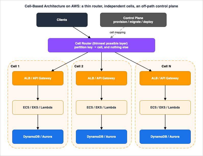
Cell-based architecture is the pattern for containing that second class of failure. It takes the fault-isolation concept AWS applies to its own Availability Zones and Regions and pushes it down into your workload: you split the workload into multiple complete, independent copies (cells), route each request to exactly one cell based on a partition key, and make sure a failure inside a cell cannot escape it. AWS has published this as formal guidance — the whitepaper Reducing the Scope of Impact with Cell-Based Architecture, publication date September 20, 2023 — and codified it in the Well-Architected Framework as REL10-BP03 Use bulkhead architectures to limit scope of impact.
That guidance poses the design question better than I can paraphrase it: "Is it better for 100% of customers to experience a 5% failure rate, or 5% of customers to experience a 100% failure rate?" Cell-based architecture is what you build when the second option is the right answer.
This article is the implementation companion to that guidance. AWS documents the concepts well; what is thin, even in English, is the layer between "a cell is an independent copy of your workload" and "here is how you pick the partition key, here is what bounds the maximum cell size, here is what the router can actually be built out of on AWS today, and here is the order in which you migrate an existing single-stack system." That gap is what this article fills.
1. Introduction: What Cells Contain, and What This Article Covers
A cell-based architecture is not a general-purpose availability improvement. It is a targeted answer to a specific list of failure modes, and it is worth being precise about which ones, because that list determines whether the investment pays back.Well-Architected names the failure classes cells are good at: "unsuccessful code deployments or requests that are corrupted or invoke a specific failure mode (also known as poison pill requests)." The whitepaper adds overload and operational mistakes. What these have in common is that they are not infrastructure failures — they are failures that your own change process, your own request handling, or one of your own tenants introduces, and that therefore appear identically in every zone and every Region you run in.
| Failure class | Contained by Multi-AZ | Contained by Multi-Region | Contained by cells |
|---|---|---|---|
| Host, rack, or single-instance failure | Yes | Yes | Yes (already, inside the cell) |
| Availability Zone impairment | Yes | Yes | Only if cells are AZ-aligned or the cell is itself Multi-AZ |
| Region-wide impairment | No | Yes | Only if cells are Region-aligned |
| Bad deployment or configuration change | No | No | Yes, if you deploy cell by cell |
| Poison pill request | No | No | Yes |
| One tenant overloading a shared resource | No | No | Yes |
| Operational mistake on a live system | No | No | Yes, scoped to the cell operated on |
| Failure of a dependency shared by all cells | No | No | No |
The last row is the honest caveat and the subject of Section 11.1. Cells only contain what is actually inside them.
What this article covers: fault isolation boundaries and static stability, the anatomy of a cell, choosing a partition key and a mapping algorithm, sizing cells against service quotas, the four practical cell-router implementations on AWS, shuffle sharding (what it is, what it requires, and where it does not apply), the data layer inside a cell, wave deployment, cell-aware observability, anti-patterns, and a staged migration path.
What it deliberately does not cover, because each already has a home:
- Multi-tenant SaaS tenant-isolation models (silo, pool, bridge, onboarding, metering) — see my AWS SaaS Multi-Tenant Architecture Guide. Cells and tenant isolation are related but different: tenant isolation is about who can read what; cells are about whose failure reaches whom.
- Multi-Region active-active implementation — see my AWS Multi-Region Active-Active Architecture Guide.
- Choosing a DR strategy — see my AWS Disaster Recovery Strategies Guide. This matters here, because cells are not a DR mechanism, and Section 3.3 explains why.
- Sharding in the sense of splitting a dataset. Shuffle sharding assigns each customer a combination of shared resources so that no two customers share the same combination; it does not divide the data. Splitting one logical database across shards is a different problem carrying the same word — see my Sharding Aurora PostgreSQL with Limitless Database.
- Pricing. Cells cost more. I keep to this site's policy of not quoting prices and describe the cost of cellularization in the terms an architect actually has to defend: operational complexity, resource overhead, and deployment count.
Every service behavior, quota, and feature status below was verified against AWS documentation while writing, on 2026-07-31. Where a number is a default service quota, it is adjustable unless stated otherwise, and you should re-check it before designing to it.
2. Fault Isolation Boundaries and Static Stability
Before deciding what a cell is, it is worth being precise about what boundaries you already have and what each of them actually contains.2.1 The boundaries AWS gives you
The AWS Fault Isolation Boundaries whitepaper enumerates the core fault containers in AWS infrastructure as partitions, Regions, Availability Zones, control planes, and data planes. Those five are the raw material. Two of them — control plane and data plane — are not geographic at all, and they are the pair most workload designs ignore.The Availability and Beyond whitepaper draws the distinction that makes the rest of this article coherent:
- Fault tolerance is the ability to withstand subsystem failure and maintain availability, typically by holding redundant capacity that can absorb 100% of a failed subsystem's work.
- Fault isolation minimizes the scope of impact when a failure does occur, by breaking the workload into modules that fail independently and can be repaired in isolation.
Multi-AZ deployment is mostly fault tolerance. Cell-based architecture is fault isolation. You need both, and buying more of one does not give you the other.
2.2 Where a cell sits in the hierarchy
| Boundary | What it contains | What it does not contain |
|---|---|---|
| Process or thread pool | A crashed worker, a leaked handle | Anything the whole fleet shares |
| Instance, task, or execution environment | A corrupted host, a bad instance | A defect in the image or code that runs on all of them |
| Availability Zone | Power, network, and physical-infrastructure events in one zone | A change deployed to all zones at once |
| AWS Region | Region-wide infrastructure events | A global configuration change; a defect in code deployed to all Regions |
| Control plane versus data plane | Failures in provisioning and change APIs, kept away from steady-state serving | Failures in the data plane itself |
| Cell | A bad deployment, a poison pill request, an overload caused by one partition key, an operational mistake — for the subset of the workload assigned to that cell | Failures in a shared dependency that every cell reaches; failures in the router |
A cell is a boundary you define and control, and it is orthogonal to the AWS-provided boundaries: the whitepaper states that a cell-based architecture "can be zonal, regional, or global." You choose whether a cell lives inside one AZ, spans the AZs of a Region, or is a Region.
2.3 Control plane, data plane, and static stability
AWS separates most services into a control plane (the APIs that create, modify, and delete resources) and a data plane (the part that does the day-to-day work). The guidance is blunt about the reliability asymmetry: "Control planes are statistically more likely to fail than data planes," because control planes are more complex and have more moving parts.A cell-based architecture has the same split:
- The control plane provisions cells, de-provisions cells, updates the cell mapping, migrates tenants between cells, and deploys code.
- The data plane is the cell router plus the cells themselves, serving requests.
Static stability is the property that the data plane keeps working correctly when the control plane is impaired. Well-Architected states it as REL11-BP04 Rely on the data plane and not the control plane during recovery. In a cell-based system this has a very concrete meaning: if your control plane is down, no new cells can be created, no tenants can be moved, and no configuration can be changed — and every existing request must still be routed and served correctly.
The whitepaper frames the same asymmetry in CAP terms: control planes are designed to fail rather than to corrupt or return incorrect information (CP), while data planes prefer to remain available even when acting on stale information (AP). The canonical implementation it gives is a router that loads the cell mapping into memory from an S3 bucket and keeps serving from that in-memory copy: "Even if the control plane, Amazon S3 or a zone is unavailable, the router is still able to direct traffic to the cells." Stale routing beats no routing.
This single idea — the router must be able to work from a cached copy of the mapping, indefinitely — constrains every router design in Section 6.
3. What a Cell Is
3.1 The three components
AWS defines the architecture as exactly three parts:| Component | Definition | Design rule |
|---|---|---|
| Cell router | "The thinnest possible layer, with the responsibility of routing requests to the right cell, and only that" | Shared across cells, so it must be simpler and more reliable than anything it fronts |
| Cell | "A complete workload, with everything needed to operate independently" | Independent, unaware of other cells, shares no state with them |
| Control plane | Provisioning, de-provisioning, and migrating cells and their customers | Must not be on the request path |
The most useful sentence in the whole whitepaper, for anyone who has to justify this to a budget holder, is this one: "Building a cell-based architecture doesn't necessarily mean having to double, triple, or more your application's infrastructure. It might be that your application has 30 hosts, and in a cell-based architecture it has the same 30 hosts, but with a cell router and with tasks that are distributed or grouped between cells."
Cellularization is primarily a re-partitioning of capacity you already have, plus a router, plus a great deal more operational tooling. The overhead is real, but it is mostly in per-cell fixed costs (a load balancer, a database cluster's minimum size, an account's baseline) and in operational surface — not in a linear multiplication of your fleet.
3.2 The independence test
The guidance sets the bar high: "In an ideal world, a cell is independent, is unaware of other cells, and does not share its state with other cells. Cells should have no dependency on each other at all (that is, no cross-cell API calls, no shared resources like databases or S3 buckets.) Even the use of separate AWS accounts is encouraged."In practice, run this checklist against a candidate design. Every "yes" is a place where a single failure can cross the boundary you just paid to build:
- Does any cell call another cell's API directly?
- Do two cells read or write the same database, table, S3 bucket, queue, or stream?
- Do two cells share a cache, a session store, or a feature-flag service?
- Do two cells share an ALB, an API Gateway stage, or a target group?
- Does a request need data from more than one cell to be answered?
- Do two cells share an AWS account, and therefore a set of account-level quotas?
- Does the cell need the control plane to be up in order to serve a request?
- Is there a shared "small" service — configuration, token validation, metering — that every cell depends on synchronously?
Items 1 through 5 are the classic ones. Item 8 is the one that actually happens. Nobody sets out to share a database between cells; everyone shares a "tiny, stable, never-changes" configuration service, and then discovers that it was the only thing all fifty cells had in common on the day it failed.
AWS's guidance on cross-cell interaction is worth applying literally: "instead of letting the cells talk directly to each other, any cross-cell calls have to go back through the normal cell router." If a call must cross the boundary, it goes back out through the front door, where it is visible, throttleable, and countable — not through a side channel that quietly makes two cells into one failure domain.
Item 6 deserves its own note. Because most AWS quotas are scoped per account per Region, an AWS account is itself a quota boundary, which is why the guidance encourages one account per cell. This is also why cell-based architecture and multi-account strategy tend to be adopted together; see my AWS Organization Guardrails with SCP and RCP guide for keeping that account fleet governed.
3.3 Single-AZ cells, Multi-AZ cells, and why cells are not failover domains
The whitepaper describes two cell-design strategies, and the trade-off is not obvious.| Single-AZ cells | Multi-AZ cells | |
|---|---|---|
| Cell boundary | One Availability Zone | The Region; the cell spans AZs |
| Advantage | You can detect precisely which AZ has a problem and mitigate for it | Wider use of Regional and serverless services; a cell is self-resilient to an AZ event without you building anything |
| Disadvantage | Requires a cell router per zone and clients that choose the correct zonal endpoint; requires services with AZ scope in their configuration; needs additional DR mechanisms to keep a cell resilient, and replicating cell state to a peer can break the cell concept | Less control over an AZ failure, particularly gray failures where some components are unstable and evacuating a zone or Region may not solve the problem |
| Blast radius of one AZ event | Every cell in that AZ — a third of your cells with three zones | No cell fails; each cell loses a fraction of its capacity |
Then comes the part that is most often misread. The whitepaper's FAQ answers "Should a Single-AZ cell fail over if an AZ becomes unavailable?" with a statement that should be on the wall of any team adopting this pattern: "Cells are implemented primarily to limit the scope of a failure's impact and not as failover domains." And, on what cells are for: "Cells were not intended to mitigate dependency failures or single points of failure. Therefore, they were not designed as failover domains."
Cells contain the failures that come from load and change. They do not, by themselves, contain a dependency failure or an infrastructure outage. If you want a Single-AZ cell to survive its AZ going away, you have to add a replica of that cell in another AZ plus a replication layer, and the whitepaper is candid that this "is more complex and driven by a much higher cost in terms of infrastructure" — and that the replication layer itself erodes the independence you built cells to get.
The practical resolution for most teams: use Multi-AZ cells, and use Amazon Application Recovery Controller (ARC) zonal shift for the AZ dimension. That gives two independent boundaries that compose cleanly — the cell contains change-and-load failures, and zonal shift handles zone impairment inside every cell at once.
A note on the current state of that service, because the naming has moved: what the 2023 whitepaper calls "Route 53 application recovery" is now Amazon Application Recovery Controller (ARC). Its zonal shift lets you shift traffic away from an impaired AZ for an Application Load Balancer or Network Load Balancer with a single action, and zonal autoshift authorizes AWS to do it on your behalf when internal monitoring indicates an AZ impairment. Two details matter for cell design:
- The behavior with cross-zone load balancing is documented explicitly in the current guide: when a zonal shift is started on an Application Load Balancer with cross-zone load balancing enabled, all traffic to targets is blocked in the affected Availability Zone and the zonal IP addresses are removed from DNS. If your load balancers have cross-zone load balancing turned off and you use a zonal shift to remove a zonal load balancer IP address, AWS documents that the affected zone also loses target capacity — so check current AZ capacity before starting one.
- Zonal shift is disabled by default and must be enabled on each load balancer. In a cell-based fleet that is a per-cell provisioning step, which means it belongs in the cell's CloudFormation or CDK template, not in a runbook.
The routing-layer mechanics of failover and the traps in health-check design are out of scope here; they live in my Amazon Route 53 DNS Architecture Guide and Route 53 Health Check and Failover - Common Pitfalls and Designs.
4. Partitioning: Choosing the Key and the Mapping Algorithm
Everything downstream — router complexity, migration pain, how evenly cells fill — is determined by the partition key. This is the decision to spend the most time on and the hardest one to change later.4.1 What makes a good partition key
AWS's criteria are precise:- The key "must be chosen to match the grain of the service, or the natural ways that a service's workload can be subdivided with minimal cross-grain interactions."
- "A good partition key is one that is easily accessible in most API calls, either as a direct parameter or a direct transformation of a parameter."
- Well-Architected adds: "The partition key must be available in all requests, either directly or in a way that could be easily inferred deterministically by other parameters."
That last constraint is stricter than it looks and is the most common reason a cellularization project stalls. If 3% of your API surface cannot name the tenant a request belongs to, then 3% of your requests cannot be routed, and you will be tempted to build a lookup in the router — which is exactly the business logic the router must not have. Fix the API before you build the cells. Section 12 puts this first in the migration order for that reason.
Common candidate keys and their failure modes:
| Candidate key | Works when | Fails when |
|---|---|---|
customerId or tenantId | Tenants are numerous and individually bounded | One customer outgrows a single cell |
resourceId such as a table, bucket, or workspace | Work is naturally per-resource and resources are bounded | A single resource becomes hot |
accountId plus Region as a composite | Multi-Region tenants that should not span cells | Cross-Region features exist |
Composite of customerId plus a business dimension | The natural second axis exists — workspace, project, product line, ledger | The second dimension is not present in every request |
| Hash of the session or user | Requests are stateless and per-user | Users share state, as with shared documents or team workspaces |
AWS calls out the big-customer problem directly: "
CustomerID might seem like a reasonable candidate partition key for many use cases, but thought needs to go into how to handle really large customers... A good strategy is to define a second dimension more aligned with your type of business to be part of the partition key." Design for that from the start; retro-fitting a composite key onto a live system means re-partitioning every tenant.4.2 Scatter-gather and cross-grain requests
Some operations genuinely go against the grain — a global search, an admin report, a cross-tenant reconciliation. The guidance accepts this: such interactions "are inevitable and need to be accommodated, but should represent the minority of the service's workload."Two rules keep them from destroying the isolation:
- Cross-cell calls go back through the router, not cell-to-cell. This keeps the dependency graph a star rather than a mesh, and keeps the traffic observable.
- Move the read off the request path entirely where you can. Stream each cell's changes to a central data lake and answer cross-cell questions from there. AWS DevOps Guidance recommends exactly this: "Stream changes to a central data lake for centralized querying and analysis of changes across all cells." A reporting query that reads a data lake cannot take a cell down; a scatter-gather that fans out to fifty cells synchronously can.
4.3 The four mapping algorithms
The whitepaper lists four partitioning algorithms "without specific recommendations." Here they are with the trade-off that actually decides between them: what happens when you add or remove a cell.| Algorithm | How it maps | Adding or removing a cell | Router state | Best for |
|---|---|---|---|---|
| Full mapping | An explicit key-to-cell entry for every partition key | Only the moved keys change; migration is fully controlled | Largest — one entry per key | Tenant populations where you need per-tenant control, quarantine, and pinning |
| Prefix and range-based mapping | Key ranges map to cells | Split or merge a range, affecting only the keys in that range | Small — a range table | Keys with meaningful lexical or numeric ordering |
| Naive modulo mapping (fixed partition number) | hash(key) mod N | Changing N remaps almost everything | Smallest — just N | Fixed cell counts that will not change, or as the first step of the two-step scheme below |
| Consistent hashing | Keys map to a large fixed number of logical buckets; buckets map to cells | Only a fraction of keys move | Moderate — a bucket-to-cell table | Cell counts that grow over time |
The consistent-hashing entry needs the detail that makes it practical. AWS describes the two-step form: "a system that is configured with a fixed large number (for example, tens of thousands) of logical buckets which are explicitly mapped to much smaller number of physical cells. Mapping a key to a cell is a two-step process. First, the key is mapped to its logical bucket using naïve module mapping. Then the cell for that bucket is located using a bucket to cell mapping table."
This is the design I would default to for a system that expects to grow its cell count: modulo into a fixed large number of buckets, then a bucket-to-cell table that the control plane owns. Adding a cell moves buckets, not keys, and the router's state is a table of small integers — trivially cacheable in memory, trivially fittable in a CloudFront KeyValueStore, and trivially diffable when it changes.
The whitepaper names the specific algorithm families for the pure form as well: the Ring Consistent Hash (Karger et al., as used in the Chord distributed hash table), A Fast, Minimal Memory, Consistent Hash Algorithm (Lamping and Veach), and multi-probe consistent hashing (Appleton and O'Reilly). It also names the ring's weakness: it "can suffer from significant high peak-to-average ratios (uneven spread)," which in cell terms means some cells fill much faster than others.
4.4 The override table is not optional
One short page in the whitepaper carries a rule that applies to every design above: "Regardless of partition mapping approach, it's important to also use an override table to force specific keys to specific cells (except for full mapping, which natively provides this support). This can be useful for testing, quarantining, and special-case routing for particularly heavy partition keys."Three uses, and all three are things you will need at three in the morning:
- Testing — pin a synthetic tenant to the canary cell so your deployment gate exercises the new code over a real request path.
- Quarantine — when one tenant is generating the poison pill, move that tenant to a cell of its own instead of letting the algorithm keep them next to paying customers.
- Heavy keys — give an outsized tenant a dedicated cell without redesigning your key.
The override table is consulted before the algorithm. It is the one piece of "logic" the router is allowed to have, because it is a lookup, not a decision.
Finally, remember whose job the mapping is: "the task of mapping a new customer to a cell and registering it in the cell router is the control plane's task." The router reads the mapping. It never computes a new assignment on the request path.
5. Sizing Cells Against Quotas
A cell has a maximum size. That is the whole point — the guidance calls this "not too big to test" and describes cells as "maximally-sized components" whose fixed cap "reduces the risk of surprises from non-linear scaling factors and hidden contention points present in scale-up systems." The question is what number to write down.5.1 The three opposing forces
AWS states them as three simultaneous constraints on cell size:- Big enough to fit the largest workloads.
- Small enough to test at full scale, and to operate efficiently — meaning a lower risk of scaling cliffs, and below the AWS account limits.
- Big enough to gain economies of scale.
And it expresses cell capacity in the terms you should publish for your own cells: how many transactions per second can a cell handle, how many customers or tenants does it support, and how many GB of transfer per second or stored capacity does it support.
5.2 Smaller cells versus larger cells
| Smaller cells | Larger cells | |
|---|---|---|
| Number of cells to operate | More replicas to manage | Fewer replicas to manage |
| Effect of one cell's outage or drain | A small percentage of the fleet | A large percentage of the fleet |
| Risk of hitting a service quota | Lower — one cell is less likely to reach Region and account limits | Higher — more computational power per cell means limits arrive sooner |
| Scope of impact | Ten cells means 10% each; a hundred cells means 1% each | A larger per-cell share of customers |
| Testability | Easier and cheaper to test to the stated limit | Harder to simulate at full scale |
| Splitting tenants | A big tenant is more likely to need splitting across cells | Fewer splits needed |
| Capacity utilization | Less idle capacity per cell, but less economy of scale | Better utilization and economy of scale |
| Operability | Requires strong automation | Easier to operate manually, which is also a trap |
Note the row that decides it for most teams: the risk of hitting a service quota. This is the most concrete input into cell size, and it is where the real design work is.
5.3 Deriving the cell maximum from quotas
Most AWS quotas are scoped per account, per Region. If a cell is an account, the quota is a hard ceiling on that cell, and the lowest non-adjustable quota on your critical path is the real maximum cell size — regardless of what your load test says.The method:
- Enumerate the AWS resources on the cell's critical request path — load balancer, API, compute, database, queue, cache.
- For each, list the account-and-Region-scoped quotas that scale with tenant count or request rate.
- Mark which are adjustable and which are not. Non-adjustable quotas are your ceiling; adjustable ones are a support-ticket lead time, which is an operational dependency you should not want during growth.
- Take the minimum, expressed in your cell's unit — tenants, or transactions per second.
- Subtract headroom. REL01-BP06 Ensure that a sufficient gap exists between the current quotas and the maximum usage to accommodate failover applies per cell. The guidance repeats it in the cell-placement context: "It is not because your cell supports 10K TPS that you must constantly be operating on the threshold of this limit."
- Load-test to the stated maximum and past it, per REL07-BP04, so the number is measured rather than assumed.
Some verified default quotas that commonly bind, as examples of what step 2 produces. Check current values before designing to them; my AWS Service Quotas cheat sheet covers the wider set.
| Service | Quota | Default | Adjustable |
|---|---|---|---|
| Application Load Balancer | Rules per Application Load Balancer | 100 | Yes |
| Application Load Balancer | Target Groups per Application Load Balancer | 100 | No |
| Application Load Balancer | Targets per Application Load Balancer | 1,000 | Yes |
| Application Load Balancer | Application Load Balancers per Region | 50 | Yes |
| API Gateway | Throttle quota per account, per Region across HTTP, REST, WebSocket, and WebSocket callback APIs | 10,000 requests per second, with burst capacity from a token bucket of maximum capacity 5,000 requests | Yes |
| API Gateway | Regional APIs per Region | 600 | No |
| API Gateway | Public custom domain names per account per Region | 120 | Yes |
| API Gateway | Routing rules per domain | 50 | Yes |
| API Gateway | Multi-level API mappings per domain | 200 | No |
| Route 53 | Records per hosted zone | 10,000 | Yes, with an additional charge above 10,000 |
| Route 53 | Hosted zones per account | 500 | Yes |
| Route 53 | Health checks per account | 200 | Yes |
| Route 53 | Geolocation, latency, multivalue answer, weighted, and IP-based records with the same name and type | 100 | — |
| CloudFront KeyValueStore | Maximum size of an individual key value store | 5 MB | — |
| CloudFront KeyValueStore | Maximum size of a key, and of a value | 512 bytes, and 1 KB | — |
| CloudFront KeyValueStore | Key value stores per account | 200 | Yes |
Two conclusions fall straight out of that table, and they separate a design that works at scale from one that does not:
- A "one DNS record per tenant" router does not scale past the record quota. Route 53's default of 10,000 records per hosted zone is a real ceiling on the per-tenant-DNS-name pattern, and the limit of 100 records with the same name and type constrains weighted and latency sets. For a hundred thousand tenants you need a mapping table, not a record per tenant.
- The router's mapping table has its own quota. A CloudFront KeyValueStore caps at 5 MB with 512-byte keys and 1 KB values. That is ample for a bucket-to-cell table of tens of thousands of entries and nowhere near enough for a full per-tenant mapping of millions. This is a concrete reason to prefer the two-step consistent-hashing scheme from Section 4.3: it makes the router's state proportional to the number of buckets, which you choose, rather than to the number of tenants, which you do not.
5.4 Cell placement
Sizing tells you how big a cell may be. Placement decides which tenant goes where, and it is the control plane's job. The guidance says the control plane needs visibility into the capacity of each cell, the used capacity of each cell, the percentage of usage of each tenant or customer, and the quotas and limits of each cell in their respective AWS account.It also lists what placement must account for: the dimensions of each cell, which might change over time or be fixed; the dimensions of each partition key, which change over time; the cost of moving a partition key between cells; and the benefit of co-tenanting certain partition keys or having affinity.
That last one is a genuine design lever and rarely discussed. Deliberately co-locating tenants that share a usage profile — for instance putting all the low-volume trial tenants together — makes the busy cells' behavior more predictable, at the price of a cell whose failure is concentrated in one customer segment. Decide it explicitly rather than letting the hash decide for you.
6. The Cell Router
The router is the hardest part of the architecture, because it is the one component that cannot be cellularized the way everything else is. AWS states the problem exactly: "In a cell-based architecture, the only component that has the shared state of all cells is the cell router. It presents itself as a single point of failure."6.1 The requirements
The whitepaper's list of "cell router features to keep in mind" is short enough to use as an acceptance test:- Be simple as possible, but not simpler.
- Have request dispatching isolation between cells.
- Minimize the amount of business logic in this layer.
- Abstract underlying cellular implementation and complexity from clients.
- Fast and reliable.
- Continue operating normally in other cells even when one cell is unreachable.
To which the guidance adds the routing recommendation — "distribute requests to individual cells using a partition mapping algorithm in a computationally efficient manner, such as combining cryptographic hash functions and modular arithmetic to map partition keys to cells" — and the reliability principle behind it, citing Colm MacCarthaigh's Reliability, constant work, and a good cup of coffee: "simple designs and constant work patterns produce reliable systems and reduce anti-fragility."
Constant work is the design idea to internalize here. A router that does the same amount of work per request regardless of what the request is, and that refreshes its whole mapping on a fixed schedule regardless of how many entries changed, has no failure mode that only appears under unusual conditions — because there are no unusual conditions. A router that does incremental updates, retries individual lookups, and has a fast path and a slow path has several.
And the scaling requirement, stated honestly: "the routing layer still has to scale infinitely, but the set of problems that you have to solve for scaling the thinnest possible layer should be a subset of the scaling challenges that non-cellularized application would have to face."
6.2 Router option 1: Amazon Route 53
The simplest form, in the whitepaper's words: "Give each tenant a custom DNS record they use to reach your service, then configure the DNS record to point at a specific cell to which the tenant has been assigned."Why it is attractive. Routing happens before a packet reaches your infrastructure, so there is no router fleet to run, scale, or deploy to. Route 53's DNS data plane is designed for extreme availability — the published Amazon Route 53 SLA measures a hosted zone's Monthly Uptime Percentage against 100%, with service credits beginning below 100%, and treats a hosted zone as unavailable only when all four virtual name servers assigned to it fail to respond to all DNS queries throughout a minute. Route 53 also combines with ARC for AZ or Region evacuation.
Where it breaks. Three places, in the order you hit them:
- The record quota (Section 5.3). A record per tenant does not survive six-figure tenant counts without a per-hosted-zone quota increase and the additional charge above 10,000 records.
- DNS caching. Reassigning a tenant to another cell means changing a record and waiting out the TTL plus whatever resolvers and clients actually do. Cell migration therefore has a mandatory quiescence window; design the migration (Section 8.3) to tolerate both cells being addressed at once.
- Provisioning latency. Creating a DNS record is a control-plane action, so onboarding now depends on the control plane being healthy. Pre-provision records in batches rather than on demand.
Use it when tenant counts are in the thousands, tenants are long-lived, and per-tenant endpoints are acceptable to your clients.
6.3 Router option 2: Amazon API Gateway routing rules
This is the option that did not exist when the whitepaper was written, and it is the cleanest managed cell router on AWS today for HTTP APIs. API Gateway custom domain names support routing rules, introduced in an AWS Compute Blog post dated June 3, 2025, which route requests from one custom domain to different target APIs and stages based on conditions.The mechanics, per the API Gateway Developer Guide:
- A custom domain has a routing mode, one of
API_MAPPING_ONLY(the default for existing domain names and any new ones you create),ROUTING_RULE_THEN_API_MAPPING, orROUTING_RULE_ONLY. - A routing rule has conditions —
MatchHeadersandMatchBasePaths— and an action naming a target API and stage. Header names are not case sensitive while header values are; base path matching is case sensitive. A single rule can include up to two header conditions and one base path condition, and all specified conditions must be met to trigger the action. - Rules are evaluated by priority, from the lowest numeric value to the highest, with 1 the highest priority and 1,000,000 the lowest. A rule with no conditions is a catch-all and should be given a high numeric value.
- The default quota is 50 routing rules per domain, which is adjustable.
Two things make this a genuine cell router rather than a routing convenience.
Wildcard domains plus the
Host header. The developer guide documents routing rules on a wildcard custom domain such as https://*.example.com that use the Host header to send a.example.com and b.example.com to different target APIs, with a catch-all for everything else. Map that onto cells and you get per-tenant subdomains routed to per-cell APIs, with the mapping held in API Gateway rather than in a fleet you operate, and with a single wildcard certificate instead of one per tenant.A zero-downtime adoption path. Set the domain to
ROUTING_RULE_THEN_API_MAPPING and existing base path mappings keep working as the fallback while you add rules one at a time, because rules are evaluated before mappings. That is precisely the migration shape you want when introducing a router into a system that already carries traffic.# Route requests for one cell's hostname to that cell's API.
aws apigatewayv2 create-routing-rule \
--domain-name 'api.example.com' \
--priority 50 \
--conditions '[
{
"MatchHeaders": {
"AnyOf": [ { "Header": "Host", "ValueGlob": "cell-003.api.example.com" } ]
}
}
]' \
--actions '[ { "InvokeApi": { "ApiId": "a1b2c3", "Stage": "prod" } } ]'Where it breaks. The 50-rules-per-domain default and the 120 public custom domain names per account per Region put a ceiling on how many distinct routes one domain can express, so this pattern routes to cells, not to tenants — the tenant-to-cell decision must already have happened, in the client's hostname or in a header set upstream. And the account-wide API Gateway throttle of 10,000 requests per second with a 5,000-request burst bucket is per account per Region, so a shared-account router is a shared throttle. Broader API type selection is in my Amazon API Gateway Decision Guide.
6.4 Router option 3: CloudFront Functions with KeyValueStore
If the cell decision must be made from something in the request that is not the hostname — a path segment, a cookie, a header carrying a tenant ID — and you want it made at the edge without a fleet, CloudFront Functions are the mechanism.- CloudFront KeyValueStore is a secure, global, low-latency key value datastore readable from within CloudFront Functions, and it lets you update the mapping data independently of the function code. Using it requires JavaScript runtime 2.0.
- The
updateRequestOrigin()helper method updates the origin settings for a request. It can point at an origin already defined in the distribution or define a new one, and the documentation notes that "the origin set by theupdateRequestOrigin()method can be any HTTP endpoint and doesn't need to be an existing origin within your CloudFront distribution." Any settings you do not specify are inherited from the existing origin's configuration.
Together those two give you a cell router that runs at CloudFront edge locations, holds the cell mapping outside the code, and selects the cell's origin per request.
import cf from 'cloudfront';

const kvs = cf.kvs();          // bucket-to-cell table, updated by the control plane

async function handler(event) {
  const request = event.request;
  const tenant  = request.headers['x-tenant-id'];
  if (!tenant) { return request; }              // catch-all cell handles unmapped requests

  try {
    const cellHost = await kvs.get(bucketOf(tenant.value));  // "cell-003.internal.example.com"
    cf.updateRequestOrigin({ domainName: cellHost });
  } catch (err) {
    // Mapping unavailable: fall through to the distribution's default origin
    // rather than failing the request. Static stability over perfect placement.
  }
  return request;
}
Where it breaks. The KeyValueStore quotas from Section 5.3 are the constraint: a 5 MB store, 512-byte keys, 1 KB values, one key value store per function, and 200 stores per account. This is a bucket-to-cell table, not a tenant-to-cell table, unless your tenant count is small. Note also that a single key value store can be associated with at most ten functions, which is a coupling to plan for if you run several distributions. Origin and cache-behavior design generally is covered in my Amazon CloudFront Origin Architecture Guide.
6.5 Router option 4: a compute layer with the mapping in memory
This is the whitepaper's own reference design, and the one to reach for when none of the managed options fit: "have the control plane write the cell mapping to an S3 bucket and a computer layer, whatever it is, it could be an EC2 instance, an Amazon ECS or Amazon EKS cluster, or AWS Lambda, whichever fits best. It is worth emphasizing that at this cellular router layer, the only responsibility should be to inspect the request data and identify which cell the request should be forwarded to."The mechanism: "the cell mapping lives in memory on the router. With each change in the S3 bucket, another process or thread is in listener mode and updates the memory map when necessary."
This design is statically stable by construction, which is why the whitepaper uses it to illustrate the control-plane and data-plane split: "Even if the control plane, Amazon S3 or a zone is unavailable, the router is still able to direct traffic to the cells." The router never blocks on a lookup; the refresh is a separate, failure-tolerant path.
Three implementation rules follow from constant work:
- Refresh the whole map on a timer, not by reacting to individual change events. A full refresh every N seconds has one behavior; an event-driven incremental update has a correct path, a missed-event path, and a reconciliation path.
- Never fail a request because the refresh failed. Serve from the last good copy and emit a mapping-staleness metric, so you can alarm on a broken refresh without the request path noticing.
- Load the map at startup and refuse to start without it — but once running, never re-acquire that dependency synchronously.
For synchronizing this kind of data plane against a control plane, AWS's own reference is the Amazon Builders' Library article Avoiding overload in distributed systems by putting the smaller service in control, which the whitepaper cites for exactly this purpose.
Non-HTTP entry points work the same way. The guidance describes a payments API exposed over Amazon SQS queues where "the cell router consumes the payment request topic and delivers it to the correct cell to carry out the transaction," with the same in-memory map refreshed from S3, and names Amazon MSK as an alternative entry point. If your workload's front door is a queue or a stream, the router is a consumer rather than a proxy — but every rule in this section still applies to it.
6.6 Making the router itself resilient
The guidance is unambiguous that the router gets the same treatment as the cells: "it is essential that it be built of with maximum reliability and also as a cellular component, regardless of whether your cell strategy is AZ independent or non-AZ independent, all the recommendations described so far and later must also be followed for the cell router. Mainly issues of service limits, size and observability."The strongest additional technique is static routing with client-side caching, which AWS Prescriptive Guidance documents as a serverless cell-router pattern: the client caches the endpoints at the initial login and subsequently establishes direct communication with the cell, contacting the router only periodically to confirm the current status or retrieve updates. The stated benefit is the one that matters: "This intentional decoupling enables uninterrupted operations for existing users in the event of cell-router downtime."
That reframes the availability requirement completely. If every existing client already knows its cell endpoint, the router is only on the path for new sessions and changed assignments, and a router outage degrades onboarding rather than taking down the service. Where your clients are your own applications — mobile apps, SDKs, agents — this is achievable and worth the protocol design. Where clients are arbitrary browsers hitting a URL, it is not, and the router is genuinely on the critical path for every request.
6.7 Choosing among the four
| Route 53 | API Gateway routing rules | CloudFront Functions with KVS | Compute with S3 mapping | |
|---|---|---|---|---|
| Where the decision is made | Resolver, before your infrastructure | API Gateway custom domain | CloudFront edge location | Your fleet |
| Routing input | Hostname only | Host and other headers, base paths | Anything in the viewer request | Anything in the request |
| Mapping state | DNS records | Routing rules, 50 per domain by default | KeyValueStore, 5 MB | In memory, refreshed from S3 |
| Change propagation | TTL-bounded | API Gateway control plane | KeyValueStore update | Your refresh interval |
| Fleet to operate | None | None | None | Yes |
| Statically stable by construction | Yes | Yes | Yes, with a fall-through default | Yes, if built per Section 6.5 |
| Main ceiling | Records per hosted zone | Routing rules per domain; account throttle | KeyValueStore size | Your own scaling |
| Non-HTTP entry points | No | No | No | Yes |
Most real designs combine two: DNS or CloudFront for the coarse, statically stable entry point, and one of the finer mechanisms for the tenant-to-cell decision. What none of them should do is consult a database on the request path to decide where a request goes. That turns your router into your least available component.
7. Shuffle Sharding
Shuffle sharding is the technique most often confused with cell-based architecture, and the confusion is worth resolving precisely, because the two solve overlapping problems at different layers.7.1 Where it comes from
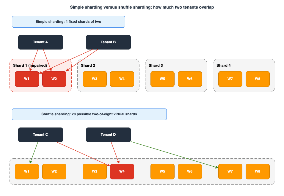
The technique was published by AWS in 2014, in the Architecture Blog post Shuffle Sharding: Massive and Magical Fault Isolation by Colm MacCarthaigh, dated 14 April 2014, describing the Route 53 Infima library. The framing is a deck of cards: "A standard deck of cards has 52 different playing cards and 2 jokers. If we shuffle a deck thoroughly and deal out a four card hand, there are over 300,000 different hands... It's also unlikely, less than a 1/4 chance, that even just one of the cards will match between the two hands."The problem it attacks is stated as clearly as the solution. Traditional horizontal scaling — spread all traffic across all healthy instances — is, in the post's words, "terrible if there's something harmful about the requests themselves: every instance will be impacted." Simple sharding improves this: divide eight instances into four shards of two, and a problem triggered by one customer affects roughly a quarter of customers instead of all of them. Shuffle sharding improves it again: instead of fixed shards, each customer is assigned a combination of instances chosen as though dealing a hand of cards, and different customers' combinations overlap only partially.
7.2 The virtual shards
The count of possible assignments is the ordinary binomial coefficient: choosingr workers out of n gives C(n, r) = n! / (r! (n - r)!) distinct shuffle shards, which AWS's own material calls virtual shards.AWS has published this arithmetic in two places, and the published figures are these:
| Source | Workers (n) | Shard size (r) | Distinct shuffle shards | Published probability that two tenants get the identical shard |
|---|---|---|---|---|
| AWS Well-Architected Framework, 2022-03-31 version of the bulkhead best practice | 8 cells | 2 | 28 | — |
| AWS Compute Blog, Handling billions of invocations - best practices from AWS Lambda | 100 queues | 2 | 4,950 | 0.02% |
| AWS Compute Blog, Handling billions of invocations - best practices from AWS Lambda | 100 queues | 3 | 161,700 | 0.0006% |
The Lambda team's summary of why this works is the operative sentence: "By distributing tenants across shards, the approach ensures that only a very small subset of tenants could be affected by a noisy neighbor. The potential impact is also minimized since each affected tenant maintains access to unaffected queues."
Notice the shape of the growth. Going from a shard size of 2 to 3 across the same 100 workers multiplies the number of distinct shards by more than thirty. This is why shuffle sharding feels disproportionate to its cost: you buy an exponential increase in isolation with a linear increase in the number of endpoints each client must be able to reach.
7.3 The precondition nobody implements
Shuffle sharding does not work on its own. The 2014 article is explicit that the isolation comes from the client, not the server: "The key to resolving this is to make the client fault tolerant. By having simple retry logic in the client that causes it to try every endpoint in a Shuffle Shard, until one succeeds, we get a dramatic bulkhead effect."And it qualifies the benefit accordingly: other customers "should experience only negligible (if any) impact if the client retries have been carefully tested and implemented to handle this kind of partial degradation correctly."
Read that as a hard requirement. If your client picks one endpoint from its shard and gives up on failure, shuffle sharding has bought you nothing — overlap on one bad endpoint is indistinguishable from being assigned to it. The design is only complete when:
- The client knows all
rendpoints in its shard. - It retries across them on failure, with a bounded attempt count and jittered backoff.
- The retry is tested against partial degradation — one endpoint slow, one returning errors, one accepting connections and never answering — and not only against a hard down.
- The retry budget is capped so a broad failure does not become a retry storm. The Amazon Builders' Library material on timeouts, retries, and backoff with jitter is the reference for getting this right.
The relationship between
r and the client's retry budget is direct: the 2014 article notes "we can shard to as many instances as we are willing to retry."7.4 Where it applies, and where it does not
The 2014 article's post-script generalizes it well: "Shuffle Sharding is a general-purpose technique, and you can also choose to Shuffle Shard across many kinds of resources, including pure in-memory data-structures such as queues, rate-limiters, locks and other contended resources."| Layer | Shuffle sharding? | Why |
|---|---|---|
| Stateless worker fleets | Yes | Any worker can serve any request, so retry across the shard is cheap |
| Queues and topics | Yes — this is what AWS Lambda does for asynchronous invocation processing, placing a message in the queue with the smallest backlog among a tenant's shard | Work is fungible, and a backed-up queue is survivable if you have another |
| Rate limiters, locks, connection pools, contended in-memory resources | Yes | Contention is the failure mode, and partial overlap dilutes it |
| Cache fleets | With care | Overlap means duplicated cached entries and a lower hit rate |
| Stateful data stores | Difficult | AWS notes shuffle sharding "can also be a bit trickier for stateful components" — the data has to be somewhere, and a shard member that does not hold the data is not a retry target, it is a miss |
| Across cells | No | See below |
7.5 Shuffle sharding versus cells
The whitepaper answers this directly in its FAQ, and the answer is a boundary rule rather than a preference: "In a cell-based architecture, a cell should be self-contained, not share its state. We can use shuffle-sharding within a cell, but cross-cells should not be used by definition."The reasoning is structural. A cell is defined by not sharing state with other cells. A shuffle shard is defined by deliberately overlapping membership. If a tenant's shuffle shard spans two cells, then those two cells both hold that tenant's state and they are no longer independent — you have spent the isolation you built cells to obtain.
So the composition is nested, not parallel:
- Between cells: each partition key maps to exactly one cell, with no overlap. That is what makes a cell's failure containable.
- Inside a cell: shuffle-shard the fungible resources — the worker pool, the queues, the rate limiters — across the tenants assigned to that cell. That is what keeps one tenant inside the cell from taking down the others in the same cell.
This nesting is also the answer to the natural objection that a cell with a thousand tenants still has a noisy-neighbor problem. It does, and shuffle sharding inside the cell is the tool for it.
One caveat on published implementations: AWS's account of building shuffle sharding into Cortex with Grafana Labs notes that the work surfaced bugs "such as global limits not applied correctly." Shuffle sharding changes which subset of resources a tenant sees, which means every global limit, counter, and fairness mechanism in the system needs re-examining against the new topology. That is not a reason to avoid it; it is a reason to budget for the audit.
8. The Data Layer Inside a Cell
Everything above is easy compared to the data. Compute is fungible; state is not, and the data layer is where cell independence is most often quietly abandoned.8.1 One cell, one set of data stores
The rule is absolute in the guidance: no shared databases, no shared S3 buckets, no cross-cell API calls. In practice this means a cell owns its DynamoDB tables, its Aurora or RDS cluster, its ElastiCache nodes, its buckets, and its queues. Not a shared cluster with a per-cell schema, and not a shared table with a cell attribute. A shared database with per-cell partitioning gives you the failure domain of one database and the operational complexity of many cells — the worst of both.Three consequences follow immediately, and each has a design answer.
No cross-cell joins or transactions. Any operation that must be atomic across two tenants in different cells is now a distributed transaction across two independent systems. The answer is not to build one; it is to choose a partition key such that the operation does not cross cells (Section 4.1), or to make the operation eventually consistent and idempotent.
Global uniqueness needs an owner. Usernames, invoice numbers, and short URLs cannot be made unique by a per-cell database. Either the control plane allocates them — which makes onboarding depend on the control plane, and that is acceptable because onboarding is a control-plane operation — or the identifier embeds the cell so that uniqueness is per-cell by construction. Embedding the cell in the identifier is usually the better trade, because it also makes every identifier self-routing: the router can determine the cell from the ID alone, with no lookup.
Cross-cell reporting moves off the request path. Stream each cell's changes to a central data lake and query there (Section 4.2). This is the one place where a shared, central component is correct — because it is asynchronous, and because nothing in the request path depends on it.
For the per-cell data tier itself, capacity modes and the DynamoDB specifics are in my Amazon DynamoDB Capacity and Global Tables Guide, and the relational high-availability options are in my Amazon RDS and Aurora High Availability Guide.
8.2 A dedicated cell per tenant is a special case, not the goal
The whitepaper's "when to use" list includes "Multi-tenant services where some tenants require fully dedicated tenancy (meaning, their own dedicated cell)." A dedicated cell is a legitimate product tier, and the override table (Section 4.4) is how you implement it without special-casing the router.But note what a dedicated cell is not: it is not tenant isolation in the security sense. A cell contains failures; it does not, on its own, enforce which identity can read which data. Those are different controls with different evidence requirements, and conflating them produces designs that satisfy neither. The isolation models — silo, pool, bridge — belong to my AWS SaaS Multi-Tenant Architecture Guide.
8.3 Moving a tenant between cells
Sooner or later a tenant outgrows its cell, a cell needs to be drained, or placement rebalancing demands a move. The guidance is candid: "Stateful cell-based architectures will almost certainly require online cell migration to adjust placement when cells are added or removed."AWS gives the phases explicitly:
- Clone the data from the current location into the new location, as a non-authoritative copy.
- Flip the new location copy to be authoritative.
- Redirect from old location to new location.
- Forget the data from the old location.
The hard part is named too: "One consideration of online cell migration is handling mapping decisions during the transitionary period. This may involve cross-cell redirects, performing multiple iterations of the mapping algorithm when necessary, or both, against different versions of the mapping algorithm state."
What that means operationally, and what to build:
- The router must be able to hold two answers for one key during the window — the old cell and the new cell — and know which is authoritative. A migrating flag plus a source and a destination is enough.
- The old cell must redirect rather than serve stale data once the flip happens. Serving from the old cell after the flip is how you get divergent writes.
- The window is bounded by your slowest cache. With DNS-based routing (Section 6.2) that is the TTL plus client behavior; with a client-cached endpoint (Section 6.6) it is your cache refresh interval. Whichever it is, Forget must not start until the window has fully elapsed.
- Every write in the window must be idempotent, because a client may retry across the flip.
The alternative the whitepaper offers avoids the dual-write problem entirely: "use careful coordination between the router and the cells, for example using the control plane to migrate clients from one cell to another and ensuring this state transition before the cell is ready to receive traffic." In other words, quiesce the tenant, move, then admit traffic. It costs the tenant a short write outage and it removes an entire class of correctness bug. For most workloads that is the right trade and the one I would default to.
The warning attached to both approaches is the important one: these mechanisms create "dependencies between cells... and therefore decrease fault isolation." Migration machinery is the most common way a permanent cross-cell dependency gets introduced. Build it so it is inert when no migration is running — no background process in the old cell polling the new one, and no standing replication link between cells that stays up after the move completes.
9. Deployment and Change Management
Cells change the deployment problem from shipping to production into shipping to N productions. The guidance does not soften this: "Now with your workload using a cell-based architecture, you have tens, hundreds or even thousands of instances of your workload to deploy and operate... In summary, it is a very complex challenge to deploy in a production environment." Its conclusion is that "it is essential to have an automated CI/CD pipeline from the beginning."That word — beginning — is the practical advice. A team that cellularizes before it automates deployment will not have a cell-based architecture; it will have N snowflakes.
9.1 The wave model
The pattern is the one AWS uses for its own service deployments: deploy in phases, one cell or set of cells at a time, and roll back the moment a signal appears. "With cell-based architecture, these are also deployed in phases... when identifying any sign of failure, you can rollback, thus reducing the number of clients that were exposed to this failure."A concrete wave structure that works:
| Wave | Contents | Bake time | Gate to proceed |
|---|---|---|---|
| 0 | The canary cell — synthetic tenants and internal traffic only, pinned there via the override table | Longer than the slowest relevant alarm's evaluation period | All per-cell alarms clear; canary success rate at baseline |
| 1 | One production cell, chosen as the smallest by tenant impact | Same | Per-cell error rate, latency, and business metric at baseline |
| 2 | About 10% of cells | Same | As above, across every cell in the wave |
| 3 | About 30% of cells | Shorter | As above |
| 4 | The remainder | — | — |
Two rules decide whether this actually protects you:
- Bake time must exceed the detection time of your slowest relevant alarm. A three-minute bake with a five-minute alarm evaluation period means the pipeline has already moved on before the first wave could possibly have told you anything. This is the most common way a wave deployment gives false confidence.
- The rollback unit is the cell — not the fleet, not the account, not the Region. If wave 2 goes bad you roll back wave 2's cells and leave the rest alone, including the already-upgraded wave 1, which means your rollback must be able to leave the fleet in a mixed-version state. That in turn means every change must be both forward and backward compatible with its neighbours for at least one version. The Builders' Library article Ensuring rollback safety during deployments is the reference for this discipline.
9.2 Canary cells
The whitepaper adds a refinement worth taking: "the first cell deployed to in a phased cell deployment can be a canary cell, and each cell can have its own canary with synthetic and other non-critical workloads to further reduce the impact of a failed deployment."Two levels, and both are useful:
- A canary cell — the first cell in the wave order, holding only synthetic and internal tenants, whose failure costs nothing.
- A canary inside every cell — synthetic transactions running continuously in each cell, so that "is cell 27 healthy?" has an answer that does not depend on cell 27 having real traffic at that moment. This matters more than it sounds: with a hundred cells, some will be quiet at three in the morning, and an error-rate metric with no denominator tells you nothing.
9.3 Making the cell reproducible
A cell must be a template instantiated with a cell identifier. If creating cell 51 involves any manual step, the architecture does not work — because creating cells is the control plane's entire job.# Cell stack skeleton: everything in a cell is parameterized by CellId, and
# nothing in it references another cell. Deployed once per cell, wave by wave.
AWSTemplateFormatVersion: '2010-09-09'
Parameters:
CellId:
Type: String
AllowedPattern: '^cell-[0-9]{3}$'
ApplicationVersion:
Type: String # Advanced one wave at a time, never fleet-wide.
CellSubnetIds:
Type: List<AWS::EC2::Subnet::Id>
Resources:
CellLoadBalancer:
Type: AWS::ElasticLoadBalancingV2::LoadBalancer
Properties:
Name: !Sub '${CellId}-alb'
Type: application
Subnets: !Ref CellSubnetIds
CellTable:
Type: AWS::DynamoDB::Table
Properties:
TableName: !Sub '${CellId}-orders' # Per-cell table. Never shared.
BillingMode: PAY_PER_REQUEST
KeySchema:
- AttributeName: orderId
KeyType: HASH
AttributeDefinitions:
- AttributeName: orderId
AttributeType: S
# Per-cell alarm. The fleet dashboard consumes these alarms, not raw metrics.
CellErrorRateAlarm:
Type: AWS::CloudWatch::Alarm
Properties:
AlarmName: !Sub '${CellId}-5xx-count'
Namespace: AWS/ApplicationELB
MetricName: HTTPCode_ELB_5XX_Count
Dimensions:
- Name: LoadBalancer
Value: !GetAtt CellLoadBalancer.LoadBalancerFullName
Statistic: Sum
Period: 60
EvaluationPeriods: 3
Threshold: 10
ComparisonOperator: GreaterThanThreshold
TreatMissingData: notBreaching
Outputs:
CellEndpoint:
Description: Registered with the control plane, which updates the router mapping.
Value: !GetAtt CellLoadBalancer.DNSNameThe template is not the interesting part; the constraints on it are. No resource in a cell stack may reference a resource in another cell stack. If you find yourself adding a cross-stack import between cells, you have found a shared dependency. The only legitimate cross-boundary reference is the control plane reading a cell's outputs in order to register it with the router, and that is a one-directional, control-plane-time operation rather than a data-plane dependency.
Related Well-Architected practices the guidance points at here are REL08-BP05 Deploy changes with automation and OPS05-BP10 Fully automate integration and deployment.
10. Observability per Cell
The guidance states the requirement in one sentence: "Your entire observability stack needs to be cell-aware." And the reason: "If you had a stack before, now you have many stacks."10.1 The cell dimension
Every metric, log line, and trace must carry the cell identifier, and the identifier must be assigned at the router and propagated inward rather than derived independently by each component:- Metrics: cell ID as a CloudWatch dimension on every custom metric. AWS service metrics get it for free if the cell owns its resources, because the resource name already contains the cell ID, as in the CloudFormation skeleton above.
- Logs: cell ID as a structured field, so a Logs Insights query can pivot by cell.
- Traces: cell ID as a trace annotation, so a trace map can be filtered to one cell.
- Requests: the guidance says it directly — "It is important to be able to track each request and identify which cell it is destined for."
The plumbing for correlation IDs, OpenTelemetry, and Application Signals is covered in my AWS Observability Architecture Guide; what follows is what is specific to cells.
10.2 Why the aggregate dashboard lies
This is the failure mode that catches teams who cellularize their infrastructure but not their monitoring.Suppose you have 50 cells and one of them is completely down. Every request to that cell fails and every tenant in it is offline. The fleet-wide error rate is 2% — under the alarm threshold of nearly every dashboard ever built, and easily inside normal variance for a system with retries. You have successfully reduced the scope of impact and simultaneously made the impact invisible.
The fixes are structural rather than cosmetic:
- Alarm per cell, then aggregate the alarms, not the metrics. Each cell gets its own error-rate, latency, and saturation alarms, with thresholds set for a single cell's traffic. The fleet view counts alarms in ALARM state. Guidance for Cell-Based Architecture on AWS describes exactly this: "a central dashboard which contains aggregated information (such as number of cells with and without errors)."
- Publish worst-cell statistics, not fleet averages. The number to put on the wall is the worst cell's availability. A mean over cells is a number no customer experiences.
- Give every cell a synthetic canary so a quiet cell still reports health (Section 9.2).
- Alarm on the count of unhealthy cells, with a low threshold. One unhealthy cell is a page; three is an incident. That is a signal a fleet-wide error rate cannot express at all.
AWS's own references for the underlying discipline are the Builders' Library articles Instrumenting distributed systems for operational visibility and Building dashboards for operational visibility, both cited by the whitepaper's observability section.
10.3 Router-specific signals
The router deserves its own instrumentation, because its failure modes are not the cells' failure modes:| Signal | Why it matters |
|---|---|
| Mapping staleness — the age of the in-memory or edge-cached mapping | Rising staleness means the refresh path is broken while the request path is still fine. The earliest possible warning, and completely invisible in request metrics |
| Unmapped-key rate | Requests arriving with a partition key the router has no assignment for. A non-zero value means onboarding is broken or a migration is half-done |
| Per-destination-cell dispatch errors | Distinguishes "the router is broken" from "cell 12 is broken", which are very different pages |
| Latency added by the router | The router must be fast, and a creeping p99 here affects 100% of traffic |
| Override-table hit rate | Quarantined and pinned tenants should be a small, known set. Growth means someone is using the escape hatch as a routing mechanism |
10.4 A change to plan around: ARC readiness checks
If you have read older material on cell-based architecture, you will have seen Amazon Application Recovery Controller (ARC) readiness checks recommended for continuously auditing whether each cell or replica is scaled and ready to take over. That advice now has a constraint.AWS documentation states: "The readiness check feature in Amazon Application Recovery Controller (ARC) is no longer open to new customers. Existing customers can continue to use the service as normal." The ARC document history records the change taking effect on April 30, 2026. The same notice is explicit that the rest of the service is unaffected: "ARC and ARC Region switch continue to be fully supported. Only the readiness check feature is affected by this change. There are no changes to Region switch, routing controls, zonal shift, and zonal autoshift."
For a cell-based design started today, that means the per-cell readiness audit is something you build:
- Quota headroom per cell — query Service Quotas for the quotas identified in Section 5.3 and compare against actual usage per cell, on a schedule. This is the check with the highest value, because quota exhaustion is exactly the failure mode cells are supposed to avoid.
- Configuration drift between cells — cells must be identical apart from their identifier and size. Compare deployed template parameters, engine versions, and runtime versions across cells; any drift is a latent failure that will surface during a wave deployment.
- Capacity readiness — can each cell absorb the load it would be asked to take if placement changed? Answering this is easier in a cell design than in a monolith, because a cell has a published maximum (Section 5.1).
Zonal shift and zonal autoshift remain the AZ-dimension tools and are unaffected, including ARC practice runs, which since June 30, 2025 can be started on demand and include checks for sufficient capacity in other Availability Zones in the Region. At the Region dimension, ARC Region switch carries its own continuous check — plan evaluation — and what its check categories read is worked through in Orchestrating Regional Failover with Amazon Application Recovery Controller Region Switch.
11. Anti-Patterns and Failure Modes
Well-Architected lists five anti-patterns for REL10-BP03 outright:- Allowing cells to grow without bounds.
- Applying code updates or deployments to all cells at the same time.
- Sharing state or components between cells, with the exception of the router layer.
- Adding complex business or routing logic to the router layer.
- Not minimizing cross-cell interactions.
Those are the headline five. Below are the ones I would add from how these designs actually fail, with the mechanism spelled out.
11.1 The shared dependency that does not count
The most reliable way to lose everything you paid for. It is never the database — everyone knows not to share the database. It is a configuration service, a feature-flag evaluator, a token introspection endpoint, a license checker, a schema registry, or a metering API. Small, stable, and "basically never changes."The moment every cell calls it synchronously on the request path, your N cells have a common failure domain of one, and your measured availability is bounded by that service's availability no matter how many cells you run.
Test for it this way: for each external dependency, ask "if this returns errors for ten minutes, how many cells stop serving?" If the answer is "all of them," it is not a dependency, it is your new single point of failure. Fix it by giving each cell its own copy, by caching the answer inside the cell with a long TTL and a stale-if-error policy, or by moving the call off the request path entirely.
11.2 A router that grew a brain
Routers acquire logic the way boats acquire barnacles. First it is authentication, because the router is already terminating TLS. Then rate limiting, because the router is the only place that sees all traffic. Then request enrichment. Then a small database call to resolve something.Each addition is defensible; the aggregate is a component more complex than the cells it protects, failing for reasons unrelated to routing. AWS's requirement — "Minimize the amount of business logic in this layer" — exists precisely because the pressure to add is constant.
The test: can you state the router's entire behavior in one sentence, and can you test it exhaustively? The guidance makes the same point positively: keeping the router simple "has the added benefit of making it easy to understand its expected behavior at all times, allowing for thorough testability."
11.3 The router that became stateful
Related but distinct. A router that must write something per request — a session, a counter, a sticky assignment — now has a write path, and write paths fail differently from read paths. The mapping must be readable from a cached copy (Section 2.3); anything that must be written synchronously belongs inside a cell.11.4 The one cross-cell call
A single cell-to-cell call, added for a feature that genuinely spans tenants. It works. Then there are three. Then the dependency graph is a mesh and a failure in cell 7 propagates to the twelve cells that call it.The rule from the guidance handles this without banning the feature: cross-cell calls "have to go back through the normal cell router." Routing through the front door means the call is visible in the router's metrics, subject to the same throttling as external traffic, and impossible to add accidentally.
11.5 Treating cells as a failover mechanism
Covered in Section 3.3 and repeated here because it is the most consequential misunderstanding: cells "were not designed as failover domains." If a design's disaster-recovery plan is "fail over to another cell," it is not a cell-based architecture — it is an active-passive pair with extra steps, and the cross-cell replication it requires has already broken the isolation. Use cells for containment and a separate, deliberate DR mechanism for recovery; my AWS Disaster Recovery Strategies Guide covers the latter.11.6 Cross-cell fallback
A specific and dangerous case of the previous two: when a cell is unhealthy, automatically send its requests to another cell. It sounds like resilience. It is a load-transfer mechanism that fires exactly when the system is already stressed, along a code path never exercised in normal operation and therefore never tested, and it can convert a one-cell failure into a cascading multi-cell failure by piling the failed cell's load onto a healthy neighbour. The Amazon Builders' Library article Avoiding fallback in distributed systems is the argument in full, and it applies with particular force here, where the fallback also violates the cell's data independence.11.7 Too many cells, not enough tooling
The one that is invisible until it is fatal. Cell count grows because cells are small and the arithmetic is attractive; the operational tooling does not grow with it. Now a security patch requires 200 deployments, an investigation requires knowing which of 200 dashboards to open, and a quota increase requires 200 support cases.The guidance flags the trade in its sizing table — larger cells are "easier to operate" — and adds the qualifier that matters: "it is important to build the necessary tools to automate the operation of cells, even environments with 'large' cells, which can grow to tens, hundreds or more cells."
A practical gate: do not add a cell if any routine operation on the fleet is still manual. The number of cells you can run is a function of your automation, not of your architecture diagram.
11.8 Correlated failure through the shared pipeline
Cells isolate runtime. They do not isolate the pipeline that produces what runs in them. A bad base image, a compromised dependency, a broken IaC module, or a configuration change pushed by fleet-wide automation reaches every cell equally — which is exactly what wave deployment (Section 9.1) exists to slow down. The Builders' Library article Minimizing correlated failures in distributed systems is the relevant reading, and the practical implication is that your wave gates have to evaluate real signals, not just whether the deployment succeeded.12. Migration Path
Almost nobody builds a cell-based architecture from scratch. The realistic starting point is one production stack, some tenants, and a growing anxiety about blast radius. This is the order I would do it in, and the order matters more than the individual steps.Step 1. Make one cell reproducible before you make two. Everything in the workload must be created by a template with no manual steps, parameterized by a cell identifier (Section 9.3). If you cannot destroy and recreate your production stack from source, you cannot create cell 2, and everything after this step is blocked. This is usually the longest step and it delivers value on its own.
Step 2. Get the partition key into every request. Choose the key (Section 4.1), then make it present and logged on every API call, before any cells exist. Log the unmapped rate. You will find the endpoints that cannot name their tenant, and fixing those is far cheaper now than when a router depends on it. Do not proceed until the unmapped rate is zero.
Step 3. Insert the router in pass-through mode. Deploy the router in front of the single existing stack, routing 100% of traffic to it. The router is now carrying production traffic while being unable to route anything wrongly, which is the only safe way to learn its real failure modes, latency contribution, and operational behavior. Run it this way for weeks, not days.
Step 4. Make the observability cell-aware. Before there is a second cell, add the cell dimension to metrics, logs, and traces, build the per-cell alarms, and build the aggregate-of-alarms dashboard (Section 10). Doing this after you have cells means running blind through the riskiest phase.
Step 5. Create cell 2 and move a small, low-risk tenant set. The point of this step is not capacity — it is to exercise the migration machinery (Section 8.3) while the stakes are low. Move tenants, verify, and move some back. If migration only works in one direction, it does not work.
Step 6. Split the deployment into waves, with cell 1 as the canary. Now that there are two cells, the deployment pipeline stops being fleet-wide. Establish the bake times and the automatic-rollback gates here, with two cells, rather than discovering they are wrong with twenty.
Step 7. Cap the cell. Derive the quota-bound maximum (Section 5.3), load-test to it and past it, publish the number, and wire the control plane to create a new cell when a cell approaches it. Only now is the architecture actually scaling out rather than up.
Step 8. Remove the last shared dependencies. The configuration service. The shared cache. The one bucket. The metering API. This is the step teams skip, because by now the architecture looks finished and the remaining shared components are small. Run the Section 3.2 checklist and the Section 11.1 test honestly. Until this step is done, your measured blast radius is still the blast radius of whatever is left shared.
Two notes on sequencing. Steps 2 and 3 have the highest ratio of value to risk — a partition key in every request and a proven pass-through router are useful even if you never build a second cell, and they are the prerequisites for everything else. And Step 4 before Step 5, always: cell-aware observability is what makes the first migration survivable.
13. Frequently Asked Questions
How many cells should I start with?
Two — and then the number that falls out of the quota-bound maximum (Section 5.3) divided by your total load, plus headroom. Starting with two is what proves the architecture actually works, because two cells force you to build the router, the migration path, the wave deployment, and the cell-aware observability, all of which are the hard parts. Going from two to twenty is a capacity exercise; going from one to two is an architecture change.Is a cell the same as an Availability Zone or a Region?
No, though it can be aligned to one. AWS states that a cell-based architecture "can be zonal, regional, or global" — the cell boundary is one you define with your partition key. AZs and Regions are boundaries AWS provides against infrastructure failures; cells are a boundary you build against failures that travel with your code, configuration, and load. They compose, and most designs use Multi-AZ cells so each cell is internally resilient to an AZ event (Section 3.3).Is shuffle sharding a replacement for cell-based architecture?
No — they operate at different layers, and AWS is explicit that they are not the same thing. The rule is: no overlap between cells, shuffle sharding inside a cell. A cell is defined by not sharing state; a shuffle shard is defined by deliberately overlapping membership, so letting a shuffle shard span cells destroys the cell's independence. Use cells to bound the impact of a bad deployment or a poison pill, and shuffle sharding inside a cell to bound the impact of a noisy tenant on the cell's fungible resources — worker pools, queues, rate limiters (Section 7.5).Can the cell router just be a load balancer?
Only if the cell decision is expressible in the routing rules the load balancer supports, and only within its quotas. An Application Load Balancer defaults to 100 rules per load balancer, so host-based or path-based routing to cells works for a modest number of cells and does not work as a per-tenant mapping. For most designs the router is DNS, API Gateway routing rules, a CloudFront function, or your own thin compute layer with the mapping in memory (Section 6). Choosing between load balancer types is covered in my AWS Elastic Load Balancing Decision Guide.What happens to a tenant whose cell is down?
They are down, and that is the design working as intended rather than failing. The value proposition of cells is that the other tenants are unaffected: "If a workload uses 10 cells to service 100 requests, when a failure occurs in one cell, 90% of the overall requests would be unaffected by the failure." If "that tenant must stay up" is a hard requirement, that is a fault-tolerance requirement, and it is met by making each cell internally redundant — Multi-AZ, multiple instances, ARC zonal shift — not by routing them to a different cell. Cross-cell failover reintroduces exactly the coupling cells exist to remove (Section 11.6).How do I answer a query that spans all cells?
Asynchronously, from a copy. Stream every cell's changes to a central data lake and query there. A synchronous scatter-gather across all cells makes every cell a dependency of one request, which inverts the isolation you built. Where a synchronous cross-cell call is genuinely unavoidable, route it back through the cell router rather than cell-to-cell, so it stays visible and throttleable (Section 4.2).Do I need one AWS account per cell?
Not strictly, but AWS encourages it, and there is a hard technical reason beyond governance: most AWS quotas are scoped per account per Region, so two cells in one account share their quota ceilings — which means a runaway tenant in cell A can exhaust a quota that cell B needs. That is precisely the failure cells are meant to contain. If you do share accounts, know exactly which quotas you are sharing and monitor them per cell.How do I know whether my workload justifies this?
AWS lists the characteristics that benefit: applications where any downtime has a huge negative impact on customers; financial-services workloads critical to economic stability; ultra-scale systems that are too big or too critical to fail; a Recovery Point Objective of less than 5 seconds; a Recovery Time Objective of less than 30 seconds; and multi-tenant services where some tenants require fully dedicated tenancy. And it lists the costs honestly — increased architectural complexity from redundant infrastructure and components, the need for specialized operational tools and practices to run many replicas of the workload, and the necessity to invest in a cell routing layer.The honest test is whether you can commit to the operational investment, not whether the diagram appeals. A cell-based architecture that is not automated is worse than the monolith it replaced. If the answer today is "not yet," Steps 1 through 3 of Section 12 are still the right work — they make the system better on their own and leave the option open.
What replaced ARC readiness checks for verifying that a cell is ready?
Your own audit. The readiness check feature in Amazon Application Recovery Controller is no longer open to new customers as of April 30, 2026, though existing customers can continue to use it, and the rest of ARC — Region switch, routing controls, zonal shift, and zonal autoshift — is unaffected. For new cell-based designs, build a scheduled audit of quota headroom per cell against Service Quotas, of configuration drift between cells, and of each cell's ability to absorb the load placement might send it (Section 10.4). In a cell architecture this is more tractable than it sounds, because a cell has a published, tested maximum.14. Summary
Cell-based architecture is AWS's answer to a specific question: how do you contain the failures that multi-AZ and multi-Region redundancy cannot touch — a bad deployment, a poison pill request, a tenant that overloads a shared resource, an operational mistake? The answer is to build a fault-isolation boundary aligned to your partition key, and then to hold it rigorously.- The boundary is only as good as its weakest shared component. A cell that shares a database, a cache, or a "small" configuration service with another cell is not a cell. Run the independence checklist (Section 3.2), and run the "if this dependency fails for ten minutes, how many cells stop serving?" test (Section 11.1) on everything.
- The partition key is the decision that cannot be undone cheaply. It must be present in every request, match the grain of the service, and have a second dimension available for tenants that outgrow a cell (Section 4.1).
- Cell size is bounded by quotas, not by ambition. Enumerate the account-and-Region-scoped quotas on the critical path, take the lowest non-adjustable one, subtract headroom, and load-test to the published number (Section 5.3).
- The router is the thinnest possible layer, and it must be statically stable. It routes and nothing else, it serves from a cached mapping when the control plane is impaired, and it keeps working for other cells when one cell is unreachable. On AWS today the four practical implementations are Route 53, API Gateway routing rules, CloudFront Functions with KeyValueStore, and a thin compute layer with the mapping in memory refreshed from S3 (Section 6).
- Shuffle sharding nests inside cells, never across them. Between cells: one key, one cell, no overlap. Inside a cell: shuffle-shard the fungible resources so one tenant cannot monopolize them — and remember that the isolation only materializes if the client retries across its whole shard (Section 7).
- Cells are containment, not failover. AWS says so directly. Pair them with a deliberate DR mechanism and with ARC zonal shift for the AZ dimension, and do not build cross-cell failover (Sections 3.3, 11.5, 11.6).
- Operate them or do not build them. Wave deployment with a canary cell and bake times longer than your slowest alarm; per-cell alarms aggregated into a count of unhealthy cells rather than a fleet-wide error rate that hides a dead cell behind a 2% average; and, since ARC readiness checks closed to new customers on April 30, 2026, your own per-cell audit of quota headroom and configuration drift (Sections 9, 10).
If you are starting today, the first three steps of Section 12 — a reproducible stack, the partition key in every request, and the router in pass-through mode — are worth doing regardless of whether you ever create a second cell. They are the parts that make the rest possible, and they improve the system on their own.
For the adjacent decisions this article deliberately delegates: choose a recovery strategy in my AWS Disaster Recovery Strategies Guide, build the most demanding multi-Region topology in my AWS Multi-Region Active-Active Architecture Guide, design tenant isolation in my AWS SaaS Multi-Tenant Architecture Guide, audit the whole workload against the pillars with my AWS Well-Architected Practical Self-Audit Checklist, and read how these failure modes look from the other side in my AWS Postmortem Case Studies and Design Lessons and Event-Driven Architecture Anti-Patterns on AWS.
15. References
- AWS Whitepaper - Reducing the Scope of Impact with Cell-Based Architecture
- AWS Whitepaper - What is a cell-based architecture?
- AWS Whitepaper - Why use a cell-based architecture?
- AWS Whitepaper - When to use a cell-based architecture?
- AWS Whitepaper - Implementing a cell-based architecture
- AWS Whitepaper - Control plane and data plane
- AWS Whitepaper - Cell design
- AWS Whitepaper - Single-AZ cells
- AWS Whitepaper - Multi-AZ cells
- AWS Whitepaper - Cell partition
- AWS Whitepaper - Consistent hashing
- AWS Whitepaper - A warning for all mapping approaches
- AWS Whitepaper - Cell routing
- AWS Whitepaper - Using Amazon Route 53
- AWS Whitepaper - Using a compute layer and Amazon S3 for cell mapping as cell router
- AWS Whitepaper - Routing no-HTTP requests
- AWS Whitepaper - About resilience of the cell router
- AWS Whitepaper - Cell sizing
- AWS Whitepaper - Cell placement
- AWS Whitepaper - Cell migration
- AWS Whitepaper - Cell deployment
- AWS Whitepaper - Cell observability
- AWS Whitepaper - FAQ: What about shuffle-sharding?
- AWS Whitepaper - Should a Single-AZ cell fail over if an AZ becomes unavailable?
- AWS Well-Architected Framework - REL10-BP03 Use bulkhead architectures to limit scope of impact
- AWS Well-Architected Reliability Pillar - REL11-BP04 Rely on the data plane and not the control plane during recovery
- AWS Well-Architected DevOps Guidance - Use cell-based architectures for granular deployment and release
- AWS Whitepaper - AWS Fault Isolation Boundaries
- AWS Whitepaper - AWS Fault Isolation Boundaries: Zonal services
- AWS Whitepaper - Availability and Beyond: Fault tolerance and fault isolation
- AWS Whitepaper - Advanced Multi-AZ Resilience Patterns
- Guidance for Cell-Based Architecture on AWS
- AWS Prescriptive Guidance - Set up a serverless cell router for a cell-based architecture
- AWS Architecture Blog - Shuffle Sharding: Massive and Magical Fault Isolation
- AWS Architecture Blog - AWS and Compartmentalization
- AWS Compute Blog - Handling billions of invocations - best practices from AWS Lambda
- AWS Compute Blog - Dynamically routing requests with Amazon API Gateway routing rules
- AWS Open Source Blog - How AWS and Grafana Labs are scaling Cortex for the cloud
- Amazon Builders' Library - Workload isolation using shuffle-sharding
- Amazon Builders' Library - Static stability using Availability Zones
- Amazon Builders' Library - Reliability, constant work, and a good cup of coffee
- Amazon Builders' Library - Avoiding overload in distributed systems by putting the smaller service in control
- Amazon Builders' Library - Avoiding fallback in distributed systems
- Amazon Builders' Library - Minimizing correlated failures in distributed systems
- Amazon Builders' Library - Automating safe, hands-off deployments
- Amazon Builders' Library - Ensuring rollback safety during deployments
- Amazon Builders' Library - Timeouts, retries, and backoff with jitter
- Amazon Builders' Library - Instrumenting distributed systems for operational visibility
- Amazon Builders' Library - Building dashboards for operational visibility
- Amazon API Gateway Developer Guide - Set the routing mode for your custom domain name
- Amazon API Gateway Developer Guide - How to use routing rules
- Amazon API Gateway Developer Guide - Examples of how API Gateway evaluates routing rules
- Amazon API Gateway Developer Guide - Quotas for configuring and running a REST API
- Amazon API Gateway Developer Guide - Amazon API Gateway quotas
- Amazon CloudFront Developer Guide - Amazon CloudFront KeyValueStore
- Amazon CloudFront Developer Guide - Helper methods for origin modification
- Amazon CloudFront Developer Guide - Quotas
- Amazon Route 53 Developer Guide - Quotas
- Amazon Route 53 Service Level Agreement
- Elastic Load Balancing - Zonal shift for your Application Load Balancer
- Elastic Load Balancing - Quotas for your Application Load Balancers
- Amazon Application Recovery Controller (ARC) - Readiness check availability change
- Amazon Application Recovery Controller (ARC) - Document history
References:
Tech Blog with curated related content
Written by Hidekazu Konishi