Elastic Fabric Adapter and the AWS Network Fabric - SRD, ENA Express, and Placement Group Design
First Published:
Last Updated:
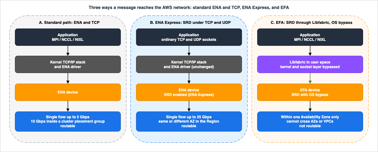
This is the failure mode that makes people buy more instances and get nothing back. It is also the failure mode that AWS built a custom network transport to address. Scalable Reliable Datagram (SRD) is that transport, and it reaches your workload through two entirely different doors: Elastic Fabric Adapter (EFA), which hands it to the application through an OS-bypass interface, and ENA Express, which slides it underneath ordinary TCP and UDP sockets without the application knowing. Same transport, different insertion point in the stack, different reach, and — critically — different workloads.
Most of the material available on these features is either an AWS product page, a single-topic post on the AWS HPC Blog, or a certification cheat sheet that stops at "ENI versus ENA versus EFA." What is thin is the layer in between: given a workload, how do you decide which fabric you need, where you have to place the instances for it to work, which instance families can carry it, what you look at when it does not work, and which mistakes silently give you a cluster that is configured for EFA and not using it.
That is what this article is. Every service behavior, limit, metric name, and API in it was verified against AWS documentation while writing, on 2026-08-04. Where AWS publishes a performance claim, I quote it as AWS's claim and attribute it — there are no measurements of my own anywhere in this article.
1. Introduction: Why Adding Nodes Stops Helping
Two workloads can move exactly the same number of bytes per second between exactly the same instances and have completely different network requirements.The first is a batch inference pipeline: a queue hands work to a fleet, each worker does its job alone, and results go to storage. If one worker is slow, the others are unaffected. Throughput is the metric that matters, and if a packet is retransmitted 200 microseconds late, nothing notices.
The second is a synchronous data-parallel training step: every node computes gradients, then all nodes participate in an all-reduce, then every node applies the same update and starts the next step. Nothing proceeds until everyone has finished. The step time is not the average node's time — it is the maximum. That single property is why tail latency, not bandwidth, is the thing that stops these workloads from scaling.
What this article covers: what makes a workload tightly coupled and why that changes which network property matters; what overhead the standard ENA and TCP path actually adds; the design principles AWS has published for SRD; EFA and its OS-bypass model, including the EFA-only interface and the EFA-to-Nitro generation mapping; ENA Express and where it applies instead; cluster, partition, and spread placement groups with their real constraints; instance selection and the topology APIs that tell you how physically close your instances actually are; the storage and checkpoint traffic that shares the same adapters; what to look at when the fabric is the bottleneck; and the failure modes that produce a cluster which is configured for EFA but not using it.
What it deliberately does not cover, because each already has a home:
- Definitions of networking primitives — ENI, security group, subnet, VPC flow log, MTU. Those are in my AWS Networking Glossary, and I use the terms here without redefining them.
- The history of the Nitro System and AWS silicon — when Nitro v4 arrived, what Annapurna Labs built, how Graviton and Trainium evolved. That is my AWS Custom Silicon History and Timeline. This article uses Nitro generations only as a capability boundary, because EFA features are gated on them.
- Instance family lineage — see my Amazon EC2 Instance Types History and Timeline.
- Running EFA through a container orchestrator. Device plugins and pod-level EFA allocation are a separate problem with a separate failure surface, and they are out of scope here; the instance-level design in this article is the prerequisite for them either way. My Self-Managed LLM Inference on Amazon EKS covers the orchestration side, and Gang Scheduling and Dynamic Resource Allocation on Amazon EKS covers the allocation path itself — the device plugin against the newer Dynamic Resource Allocation route, and what decides which one a cluster can use.
- Pricing. I keep to this site's policy of not quoting prices. The decision to adopt EFA is argued here in the terms an architect actually has to defend: collective-communication latency, scaling efficiency, and how tightly coupled the job really is.
- The internals of SRD that AWS has not published. I describe the design principles AWS has stated publicly and stop there. Speculating about the wire format or the congestion-control algorithm would be inventing facts.
One framing note before the details. It is tempting to treat "EFA" as a checkbox that makes the network fast. It is not. EFA is a different programming model that a specific class of application can exploit, gated on instance type, placement, security group configuration, driver installation, and library version — and if any one of those is wrong, you get a working cluster that quietly runs on ordinary TCP. Section 11 is the list of ways that happens.
2. What Tightly Coupled Means
"Tightly coupled" is used loosely enough that it is worth pinning down, because the definition determines which fabric you need.2.1 The communication pattern, not the byte count
A workload is tightly coupled when progress on any node depends on messages from other nodes within the same iteration. The canonical shapes are:- Collective operations — all-reduce, all-gather, reduce-scatter, broadcast, all-to-all. Every participant contributes and every participant waits. Data-parallel training uses all-reduce on gradients; tensor-parallel and expert-parallel layouts use all-gather and all-to-all inside a single forward pass.
- Neighbor exchange with a synchronization barrier — the classic HPC domain-decomposition pattern. Each rank exchanges halo cells with its neighbors, then the timestep advances only when all have exchanged.
- Fine-grained request/response between ranks — many small messages with a dependency chain, where each round trip is on the critical path.
What these have in common is a synchronization point. Between two synchronization points, nodes work independently; at the barrier, the slowest one sets the pace for all of them.
Compare that with a loosely coupled workload — an embarrassingly parallel batch job, an asynchronous inference pipeline, a fleet behind a load balancer. There, one slow worker delays one unit of work. The architecture for that class is a different problem entirely, and I have written it up separately in my Large-Scale Batch Generative AI Pipeline on AWS.
2.2 Why the tail dominates
Consider one collective operation across N ranks. The operation completes when the last message arrives. If each rank's message latency is drawn from some distribution, the collective's latency is the maximum of N draws — which means it is governed by the upper tail of the distribution, and the effective percentile you are sampling gets worse as N grows.That is the structural reason why a fabric with a good median and an ugly tail scales badly, and a fabric with a slightly worse median and a tight tail scales well. It is also why "we have 100 Gbps of bandwidth" answers the wrong question: at the message sizes typical of a gradient all-reduce chunk, the collective is latency-bound long before it is bandwidth-bound.
The mechanism that produces the ugly tail on a conventional stack is head-of-line blocking. TCP delivers bytes in order. A single lost packet at the front of the queue stalls everything behind it until it is recovered, even though the later packets have already arrived. On a large fabric with many possible paths, one congested link therefore does not just slow one flow — it injects a long tail into every flow that happens to be pinned to it, because a TCP flow is pinned to a path by its five-tuple hash.
2.3 The design consequence
If your workload is tightly coupled, three things follow, and they structure the rest of this article:- You care about the tail of message latency, so you want a transport that avoids head-of-line blocking and can route around congestion (Sections 4, 5, 6).
- You care about physical proximity, because propagation and switching hops are latency you cannot optimize away in software (Sections 7, 8).
- You care about consistency, so a node that is arbitrarily far away, or one that is being throttled, damages every iteration and not just its own (Sections 10, 11).
If your workload is not tightly coupled, the honest answer is that most of this article does not apply to you, and Section 6 is where you should look.
3. The Standard Path — ENA, the Kernel, and TCP
Before looking at what EFA removes, it is worth being precise about what the ordinary path does.3.1 What the packet traverses
On a standard configuration, AWS documents the sequence plainly: AI/ML applications use NCCL and NIXL, HPC applications use MPI, and those libraries interface with "the operating system's TCP/IP stack and the ENA device driver to enable network communication between instances."Each of those layers is doing real work — socket buffers, segmentation, congestion control state, interrupt handling, context switches between user space and kernel space, and at least one copy. For a web request measured in milliseconds this is invisible. For a collective operation whose useful work is measured in tens of microseconds, the stack is a meaningful fraction of the total.
The Elastic Network Adapter (ENA) itself is not the problem. ENA is the enhanced-networking device that provides all the IP networking and routing features a VPC needs, and AWS supports it on all Nitro-based instance types. The problem is everything between the application and the adapter.
3.2 The limits that bite before bandwidth does
Instance network performance is not one number, and the ones that constrain tightly coupled jobs are rarely the headline figure.Single-flow bandwidth. AWS documents that "When instances are not in the same cluster placement group, bandwidth for single-flow traffic is limited to 5 Gbps," and that within a cluster placement group instances "can use up to 10 Gbps for single-flow traffic." A flow here is precisely defined: "A single-flow is considered a unique 5-tuple TCP or UDP flow. For other protocols following the IP header, such as
GRE or IPsec, the 3 tuple of source IP, destination IP, and next protocol is used to define a flow." So a single TCP connection between two ranks is one flow, and if your communication library opens only a few connections per peer, your aggregate instance bandwidth is irrelevant — you are capped per flow. AWS lists exactly three ways out: a cluster placement group for up to 10 Gbps, Multipath TCP across multiple paths between two endpoints, or ENA Express for up to 25 Gbps (Section 6)."Up to" bandwidth and network I/O credits. AWS documents that "Typically, instances with 16 vCPUs or fewer (size
4xlarge and smaller) are documented as having 'up to' a specified bandwidth," and that those instances "can use a network I/O credit mechanism to burst beyond their baseline bandwidth" for "a limited time, typically from 5 to 60 minutes, depending on the instance size." Three details from that page matter operationally: there are separate credit buckets for inbound and outbound traffic; a stopped instance does not earn credits; and "Instance burst is on a best effort basis, even when the instance has credits available, as burst bandwidth is a shared resource." A cluster that looks healthy for the first few minutes of a job and degrades afterwards is often a cluster that exhausted burst credits — which is one reason a smaller size in a family behaves nothing like the largest size in the same family.Per-instance allowances other than bandwidth. The ENA driver exposes counters for allowances that are enforced independently of aggregate bandwidth:
| Counter | What exceeding it means |
|---|---|
bw_in_allowance_exceeded / bw_out_allowance_exceeded | Packets queued or dropped because aggregate inbound or outbound bandwidth exceeded the instance maximum |
pps_allowance_exceeded | Packets queued or dropped because the packets-per-second allowance was exceeded — enforced separately from bandwidth, so a small-packet workload can hit it while well under the bandwidth limit |
conntrack_allowance_exceeded | Packets dropped because the tracked-connection allowance was exhausted; new sessions then fail to establish |
linklocal_allowance_exceeded | Packets dropped for local services (DNS resolver, instance metadata, time sync) exceeding their PPS allowance — this allowance is the same across instance sizes |
AWS notes that these counters can increment even when average utilization looks low, because of microbursts — spikes lasting seconds, milliseconds, or microseconds, which per-minute CloudWatch metrics cannot resolve. A tightly coupled job is almost entirely microbursts: it is silent, then every rank transmits at once at the barrier.
Traffic that leaves the instance's neighborhood. For multi-flow traffic going through an internet gateway or a local gateway, AWS documents that instance types with fewer than 32 vCPUs are limited to 5 Gbps, instance types with more than 32 vCPUs are limited to 50% of the available bandwidth for the type, and a specific list of network-optimized types — C8in, C8ine, M8in, M8ine, M8idn, R8in, R8idn — is limited to the baseline bandwidth for the type. For cluster placement groups specifically, "Network traffic to the internet and over an Direct Connect connection to on-premises resources is limited to 5 Gbps."
3.3 The honest summary of the standard path
The standard path is correct, universal, routable, and observable. It carries your SSH sessions, your orchestration, your metrics, and your object storage traffic, and nothing in this article suggests replacing it. What it is not is a low-jitter fabric for microsecond-scale collectives — and for a loosely coupled workload, that does not matter at all.4. SRD as a Transport
AWS built a transport protocol for this problem rather than tuning the existing one. Its published design principles are worth reading carefully, because they explain exactly which workloads benefit and which do not.4.1 What AWS has said about the design
On the AWS HPC Blog, in the post In the search for performance, there's more than one way to build a network, AWS describes the reasoning behind SRD directly. Three points from that post matter for design decisions.It is Ethernet-based. AWS writes: "SRD is an Ethernet-based transport. We have a massive investment in Ethernet, which provides as such a depth and breadth of control over outcomes that we don't want to give it up." SRD is not a separate physical fabric bolted onto EC2; it runs on the same network everything else runs on.
It gives up in-order delivery on purpose. In AWS's words: "we relaxed the requirement for in-order packet delivery in the belief that if it's necessary we can re-assert it in the higher layers of the stack." This is the single most consequential design choice, and it is the reason the transport cannot simply be swapped in underneath an arbitrary application — the layer above has to be able to cope with, or restore, ordering.
AWS attributes a large tail-latency improvement to that choice. The post states: "The p99 tail latency plummeted (by around a factor of 10)." AWS explains the mechanism as follows: "Without the conga line model, SRD can push all the packets making up a block of data all at once, over all the possible pathways in our fabric (in practice, for memory reasons, we choose 64 paths at a time from the hundreds or even thousands available). This means that we don't suffer from head of line blocking, where a single-packet loss at the front of the transmit queue causes everyone else to stall while the packet is recovered."
This is AWS's published claim about AWS's own network, and I quote it as such. It is not a measurement I made, it is not reproducible from this article, and it should not be cited as an independent result. What it is good for is understanding the shape of the benefit: SRD is designed to compress the tail, not primarily to improve the median.
4.2 What the current documentation says
The EC2 User Guide describes SRD in operational rather than historical terms: it is "a high performance network transport protocol that uses dynamic routing to increase throughput and minimize tail latency," which "distributes packets for each network flow across different AWS network paths, and dynamically adjusts distribution when it detects signs of congestion," and which "manages packet reordering on the receiving end."The AWS Well-Architected Performance Efficiency Pillar makes the same point as a protocol-selection decision, under PERF04-BP05 Choose network protocols to improve performance. It describes SRD as optimized for high-throughput workloads because of its ability to spread traffic across multiple paths and recover quickly from packet drops or link failures, and then states where it belongs: "SRD is therefore best used for high performance computing (HPC) workloads that require high throughput and low latency communication between compute nodes. This might include parallel processing tasks such as simulation, modeling, and data analysis that involve a large amount of data transfer between nodes."
4.3 Where SRD shows up in AWS today
SRD is not a single-product technology. When AWS announced ENA Express support across Availability Zones on May 11, 2026, the announcement noted that "Amazon Elastic Block Store (EBS) io2 Block Express and Elastic Fabric Adapter (EFA) for high performance computing and machine learning workloads also leverage SRD."That gives three distinct surfaces:
| Surface | How the application reaches SRD | Scope |
|---|---|---|
| EFA | Through Libfabric, bypassing the kernel entirely | Within one Availability Zone; EFA traffic cannot cross Availability Zones or VPCs |
| ENA Express | Transparently, underneath ordinary TCP and UDP sockets | Between instances in the same Region, in the same or different Availability Zones |
| Amazon EBS io2 Block Express | Not exposed to the application; it is internal to the volume's data path | Block storage attachment |
The rest of this article is about the first two, because those are the ones you make a design decision about. The storage one is covered from the volume side in my Amazon EBS Performance Engineering guide.
5. EFA — OS Bypass for Tightly Coupled Workloads
5.1 What an EFA actually is
An Elastic Fabric Adapter is a network device you attach to an EC2 instance. AWS's own framing is useful: EFA "provides lower and more consistent latency and higher throughput than the TCP transport traditionally used in cloud-based HPC systems," and "the EFA device provides capabilities like built-in OS-bypass and congestion control through the Scalable Reliable Datagram (SRD) protocol."The important word is bypass. With EFA in play, AWS documents that AI/ML applications use NCCL and NIXL and HPC applications use MPI "to interface directly with the Libfabric API. The Libfabric API bypasses the operating system kernel and communicates directly with the EFA device to put packets on the network."
Libfabric is not an AWS component — it is "a core component of the OpenFabrics Interfaces (OFI) framework, which defines and exports the user-space API of OFI." That matters for portability: an application already written against Libfabric, MPI, or NCCL does not need to be rewritten for EFA, because the EFA provider plugs in underneath an interface those libraries already speak.
5.2 EFA with ENA, and EFA-only
An EFA device can be attached in two ways, and the difference is not cosmetic:| Property | ENA | EFA (EFA with ENA) | EFA-only |
|---|---|---|---|
| Supports IP networking functionality | Yes | Yes | No |
| Can be assigned IPv4 or IPv6 addresses | Yes | Yes | No |
| Can be the instance's primary network interface | Yes | Yes | No |
| Counts towards the instance ENI attachment limit | Yes | Yes | Yes |
| Instance type support | All Nitro-based instance types | EFA-supported types | EFA-supported types |
| Parameter name in EC2 APIs | interface | efa | efa-only |
| Field name in the EC2 console | No selection | EFA with ENA | EFA-only |
An EFA-only interface exists because on instances with many network cards, giving every card a full ENA device consumes IP addresses you may not have to spare and creates IP interfaces the operating system then has to reason about. AWS's recommended baseline configuration is explicit:
- For the primary network interface (network card index
0, device index0), create an ENA interface. You cannot use an EFA-only network interface as the primary network interface. - If network card index 0 supports EFA, create an EFA-only network interface for network card index
0, device index1. - For each additional network interface, use the next unused network card index with device index
0for an EFA-only interface, and/or device index1for an ENA interface depending on ENA bandwidth or IP address requirements.
This is expressed at launch as a repeated
--network-interfaces argument:aws ec2 run-instances \
--instance-type p5.48xlarge \
--count 1 \
--key-name key_pair_name \
--image-id ami-0abcdef1234567890 \
--network-interfaces \
"NetworkCardIndex=0,DeviceIndex=0,Groups=security_group_id,SubnetId=subnet_id,InterfaceType=interface" \
"NetworkCardIndex=0,DeviceIndex=1,Groups=security_group_id,SubnetId=subnet_id,InterfaceType=efa-only" \
"NetworkCardIndex=1,DeviceIndex=0,Groups=security_group_id,SubnetId=subnet_id,InterfaceType=efa-only" \
"NetworkCardIndex=2,DeviceIndex=0,Groups=security_group_id,SubnetId=subnet_id,InterfaceType=efa-only"AWS documents the same structure for launch templates via
NetworkInterfaces, which is what you want in practice, because a cluster is not launched by hand.A resource-sharing consequence worth planning around. AWS states for P6-B300 instances that the primary network card supports only an ENA interface with up to 350 Gbps of bandwidth, secondary cards support up to 400 Gbps EFA and up to 220 Gbps ENA — and, critically, "Since EFA and ENA traffic share the same underlying resources, bandwidth used by one will reduce the bandwidth that is available to the other." Your checkpoint write and your all-reduce are competing for the same adapters. Section 9 comes back to this.
5.3 Generations: EFA v1 through v4, mapped to Nitro
The EFA supported-instance-type table is organized by Nitro generation, and the capability differences are real:| EFA generation | Nitro generation | RDMA read | RDMA write |
|---|---|---|---|
| EFA v1 | Nitro v3 | No (except p4d.24xlarge and p4de.24xlarge, which support read) | No |
| EFA v2 | Nitro v4 | Yes | Yes |
| EFA v3 | Nitro v5 | Yes | Yes on most; c7gn and hpc7g sizes are read-only |
| EFA v4 | Nitro v6 | Yes | Yes |
AWS summarizes the boundary as: "EFA supports RDMA (Remote Direct Memory Access) write on most supported instance types that have Nitro version 4 and later. RDMA read is supported on all instances with Nitro version 4 and later."
This matters more than it looks. Several EFA driver metrics that tell you whether the fabric is struggling — the SRD retransmit and connection-health counters in Section 10 — are documented as available only on "Nitro v4 and later instance types that support EFA." Choosing a Nitro v3 instance for an EFA cluster therefore gives up both RDMA and a large part of your ability to diagnose the fabric.
For the history of how the Nitro generations came about, see my AWS Custom Silicon History and Timeline; here the generations are only a capability gate.
5.4 Supported interfaces, libraries, and operating systems
AWS documents EFA support for the following interfaces and libraries, with minimum versions:- Open MPI 4.1 and later
- Intel MPI 2019 Update 5 and later
- NVIDIA Collective Communications Library (NCCL) 2.4.2 and later
- NVIDIA Inference Xfer Library (NIXL) 1.0.0 and later
- AWS Neuron SDK version 2.3 and later
AWS also documents which Libfabric versions those integrate with: NCCL and MPI integrate with Libfabric 1.7.0 and later, while NIXL integrates with Libfabric 1.21.0 and later. If you are building an inference topology that uses NIXL for disaggregated prefill and decode, the Libfabric floor is much higher than the one you may have inherited from an older HPC image.
Operating system support at the time of writing covers Amazon Linux 2023; RHEL 8, 9, and 10; Debian 11, 12, and 13; Rocky Linux 8 and 9; Ubuntu 22.04, 24.04, and 26.04; and SUSE Linux Enterprise 15 SP2 and later — on both x86_64 and arm64. AWS adds the caveat that some of these may not be supported with Intel MPI, and points you at Intel's documentation for that.
5.5 The limitations, in full
These are the constraints AWS documents, and each of them is a design constraint rather than a footnote:- RDMA write is not supported on all instance types (see the generation table above).
- EFA traffic between P4d, P4de, and DL1 instances and other instance types is not supported.
- Instance types with multiple network cards can be configured with one EFA per network card. All other supported instance types support only one EFA per instance.
c7g.16xlarge,m7g.16xlarge, andr7g.16xlargeDedicated Instances and Dedicated Hosts are not supported when an EFA is attached.- EFA traffic cannot cross Availability Zones or VPCs. This does not apply to normal IP traffic from the ENA device of an EFA interface.
- EFA traffic is not routable. Normal IP traffic from the ENA device of an EFA interface remains routable.
- EFA is not supported on AWS Outposts.
- On Windows, the EFA device of an EFA-with-ENA interface is supported only for applications based on the AWS Cloud Digital Interface SDK. Attach one to a Windows instance for anything else and it functions as an ENA interface, without the EFA device capabilities. The EFA-only interface is not supported by AWS CDI based applications on Windows or Linux.
Throughout, AWS uses "EFA traffic" to mean specifically the traffic transmitted through the EFA device of either interface type — the ENA side of an EFA-with-ENA interface keeps behaving like ordinary VPC networking.
There is one more constraint that lives in the attach documentation rather than the limitations list, and it catches people: "You can attach an EFA to any supported instance that is in the
stopped state. You cannot attach an EFA to an instance that is in the running state." EFA is a launch-time or stopped-instance decision. You cannot retrofit it onto a live cluster.5.6 The setup, and the one command that proves it worked
The EFA software stack is installed from a signed tarball published by AWS. The documented flow is to build one instance, install the stack, create an AMI, and launch the cluster from that AMI — which is the right shape, because you do not want the driver installation to be part of every node's boot path.curl -O https://efa-installer.amazonaws.com/aws-efa-installer-latest.tar.gz
wget https://efa-installer.amazonaws.com/aws-efa-installer.key && gpg --import aws-efa-installer.key
gpg --fingerprint key_valueAWS documents that the fingerprint returned should be identical to
4E90 91BC BB97 A96B 26B1 5E59 A054 80B1 DD2D 3CCC, and instructs you not to run the installation script if it does not match. A checksum-based alternative is documented for environments where GPG is inconvenient.Two setup details are easy to skip and both break things silently:
- ptrace protection. AWS documents a step to disable ptrace (process trace) protection, which Ubuntu distributions enable by default, "so that Libfabric works properly."
- Confirming installation. The documented check is:
fi_info -p efa -t FI_EP_RDMwhich should return information about the Libfabric EFA interfaces, for example:
provider: efa
    fabric: EFA-fe80::94:3dff:fe89:1b70
    domain: efa_0-rdm
    version: 2.0
    type: FI_EP_RDM
    protocol: FI_PROTO_EFA
Run this on every node, in your cluster bring-up automation, and fail the job if it returns nothing. An empty result means the job is about to run over TCP while every dashboard says the cluster is healthy. This is the single highest-value check in this article.
5.7 The security group rule that is not optional
AWS states it flatly: "An EFA requires a security group that allows all inbound and outbound traffic to and from the security group itself."Both directions. The documented procedure adds an inbound rule of type All traffic whose source is the security group's own ID, and then a separate outbound rule of type All traffic whose destination is the same security group ID. Getting only the inbound half is a common and very confusing failure, because ordinary IP connectivity between the nodes keeps working — SSH succeeds, the orchestrator sees healthy nodes — while EFA traffic does not flow.
Note also that the documented example additionally opens inbound SSH from any IPv4 address, and AWS explicitly marks that as "intended for testing purposes only," recommending you restrict it to your own address range in production. Do not lift the tutorial security group into a production template. For the general shape of security group and NACL troubleshooting, see my AWS VPC Network Troubleshooting Guide.
6. ENA Express — SRD for Ordinary TCP and UDP Applications
EFA requires an application that speaks Libfabric, directly or through MPI, NCCL, or NIXL. Most applications do not. ENA Express is the answer for those.6.1 What it does
AWS describes it as: "ENA Express is powered by AWS Scalable Reliable Datagram (SRD) technology... With ENA Express, you can communicate between two EC2 instances in the same Availability Zone or across Availability Zones within the same Region."The EC2 FAQ puts the contrast with EFA in one sentence: "EFA is a network interface built for HPC and ML applications, and it also leverages the SRD protocol. EFA requires a different network programming model, which uses the LibFabric interface to pass communication to the ENI. Unlike EFA, ENA Express helps you run your application transparently on TCP and UDP."
The documented benefits are:
- Increases the maximum bandwidth a single flow can use from 5 Gbps up to 25 Gbps within the same Region, up to the aggregate instance limit
- Reduces tail latency of network traffic between EC2 instances in the same Availability Zone, especially during periods of high network load
- Detects and avoids congested network paths
- Handles some tasks directly in the network layer, such as packet reordering on the receiving end, and most retransmits that are needed, which frees up the application layer for other work
That third bullet is why "the application does not need to change": SRD relaxes ordering on the wire, and ENA Express restores it at the receiver before the bytes reach the socket. Notably, AWS documents that "ENA Express reorders network packets on the receiving end by default," and that because some UDP-based applications are deliberately built to tolerate out-of-order packets and would rather not pay for that reordering, UDP is a separate opt-in: "ENA Express supports TCP by default. UDP can optionally be enabled through an API argument or within the console."
6.2 The cross-Availability-Zone change
This is the part most existing write-ups have not caught up with. On May 11, 2026, AWS announced that "ENA Express now supports traffic between Amazon EC2 instances in different Availability Zones within a Region, delivering up to 25 Gbps single-flow bandwidth," and framed the motivation as: "Workloads such as distributed storage, databases, and file systems require deployments spanning multiple Availability Zones for resilience, yet single flows between zones support up to 5 Gbps with ENA."Three qualifications belong with that, and all three come from the current documentation:
- The tail-latency benefit is documented for the same Availability Zone. The benefits list says ENA Express "Reduces tail latency of network traffic between EC2 instances in the same Availability Zone," and the detailed text says "Longer running processes in the same Availability Zone will experience reduced tail latency during periods of network congestion." The single-flow bandwidth increase is what is documented Region-wide.
- Cross-Availability-Zone support is not everywhere. AWS documents that "ENA Express support for traffic between Availability Zones is not available in South America (São Paulo), Middle East (Bahrain), and Middle East (UAE)."
- ENA Express traffic cannot be sent in a Local Zone.
A documentation caveat, because you will run into it: the Amazon EC2 instance network bandwidth page still frames the ENA Express option as "Configure ENA Express for eligible instances within the same Availability Zone to achieve up to 25 Gbps between those instances," which reflects the pre-May-2026 behavior. The ENA Express feature page and the announcement both describe cross-Availability-Zone support. Where two AWS pages disagree, the feature's own page and the dated announcement are the ones to design against, and this is a good reason to re-check the ENA Express page rather than a summary of it.
The resulting asymmetry with EFA is the single most useful thing to hold in your head about these two features: EFA traffic cannot cross an Availability Zone; ENA Express can. They are not two settings for the same thing.
6.3 The conditions, and the silent fallback
ENA Express is enabled per network interface attachment, and AWS is careful about that word: "ENA Express settings apply to the attachment. If the network interface is detached from the instance, the attachment no longer exists, and the ENA Express settings that applied to it are no longer in force. The same is true when an instance is terminated, even if the network interface remains."For traffic to actually use SRD, AWS documents that all of the following must hold:
- Both sending and receiving instance types are supported.
- Both sending and receiving instances must have ENA Express configured.
- The sending and receiving instances must run in the same Region.
- The network path between the instances must not include middleware boxes — "ENA Express doesn't currently support middleware boxes."
- On Linux, driver version 2.2.9 or higher to use the full bandwidth potential, and 2.8 or higher to produce metrics.
And then the critical sentence: "If any requirement is unmet, the instances use the standard TCP/UDP protocol but without SRD to communicate." There is no error. The connection works. It is simply not using SRD.
AWS documents the mixed-configuration case explicitly. If instance 1 has ENA Express enabled with UDP enabled, and instance 2 has ENA Express enabled with UDP disabled, TCP between them can use ENA Express while UDP between them falls back to standard ENA transmission. Half-configured fleets produce half-configured behavior, per protocol.
6.4 The other side of the trade-off, stated honestly
AWS documents a downside, and it deserves to be quoted rather than paraphrased away: "During periods of time when network traffic is light, you might notice a slight increase in median packet latency (tens of microseconds) when the packet uses ENA Express."And the guidance that follows from it: "If your application has high packets-per-second requirements and needs to optimize for latency during uncongested periods, Enhanced networking might be a better fit."
So ENA Express is a tail-versus-median trade. If your workload's pain is p99.9 under load, you win. If your workload's pain is the median on an idle network, you may lose. That is a design decision, not a default.
For the workloads it does suit, AWS's guidance is specific: the EC2 FAQ says "ENA Express works best for applications requiring high, single-flow throughput, like distributed storage systems and live media encoding," and the AWS Networking blog post on real-world use covers in-memory databases, file systems, and media encoding.
6.5 MTU and host tuning
ENA Express adds encapsulation, and that has an MTU consequence AWS documents directly: "ENA Express requires a lower MTU than the default to accommodate additional AWS SRD headers. Newly established TCP connections automatically clamp the MSS to mitigate this, but UDP traffic still requires a lower MTU." The launch blog used8900 as the working MTU, and the EC2 FAQ says the same: "if you are using Jumbo Frames, you must adjust your maximum MTU to 8900 to use ENA Express."Rather than tuning host settings by hand, AWS publishes a settings-check script and documents what it validates: MTU size, TCP output queue size limit, whether byte queue limits (BQL) are disabled on the interface, whether TCP autocorking is disabled, transmit queue size and the Large Low Latency Queue setting, receive queue size, TCP and socket buffer sizes, and TCP congestion control configuration. It also reports the ENA driver version and ENA SRD statistics. Using the published script is strictly better than assembling this list yourself, because the list changes.
6.6 Choosing between the two doors
| Question | EFA | ENA Express |
|---|---|---|
| Does the application need modification? | It must use Libfabric, MPI, NCCL, NIXL, or Neuron | No — TCP and UDP, transparently |
| What is the programming model? | OS bypass, user space to device | Ordinary sockets through the kernel |
| Can traffic cross an Availability Zone? | No | Yes, within the Region (three Regions excepted) |
| Is the traffic routable? | No | Yes |
| Where is it configured? | Interface type at launch, or attach to a stopped instance | Per network interface attachment, enable at launch or modify |
| What does a misconfiguration look like? | Falls back to TCP over the ENA device | Falls back to standard ENA transmission |
| Typical fit | Synchronous collectives, MPI, distributed training | Distributed storage, databases, file systems, media encoding |
| Downside to plan for | Setup complexity, AZ confinement, instance-type gating | Possible small median-latency increase when the network is quiet |
If you take one thing from this section: they are not two options you pick between by trying both. They serve different applications. The question "EFA or ENA Express?" almost always resolves to "what does my communication library speak?"
7. Placement Groups
Choosing the transport is half the problem. The other half is where the instances physically are, because no transport removes propagation delay or switching hops.7.1 The three strategies, and what each is actually for
EC2 offers three placement strategies plus a fourth that is about clocks rather than proximity. They optimize for opposite things, and picking by name rather than by property is a common error.Cluster. AWS defines it as "a logical grouping of instances within a single Availability Zone. Instances are not isolated to a single rack. A cluster placement group can span peered virtual private networks (VPCs) in the same Region. Instances in the same cluster placement group enjoy a higher per-flow throughput limit for TCP/IP traffic and are placed in the same high-bisection bandwidth segment of the network."
Two phrases in that definition are doing a lot of work. "Not isolated to a single rack" is a warning against assuming a cluster placement group is a rack — it is not, and it gives you no rack-level fault isolation. "The same high-bisection bandwidth segment of the network" is the actual benefit: the group is placed where the fabric can carry all-to-all traffic without oversubscription becoming the limit.
Partition. AWS divides the group into logical segments and "ensures that each partition within a placement group has its own set of racks. Each rack has its own network and power source. No two partitions within a placement group share the same racks." This is a fault-isolation tool, aimed at replicated distributed systems — AWS names HDFS, HBase, and Cassandra — and it exposes which instance is in which partition so that topology-aware applications can make replica-placement decisions.
Spread. "A group of instances that are each placed on distinct hardware," recommended "for applications that have a small number of critical instances that should be kept separate from each other." Rack-level spread works in Regions and on Outposts; host-level spread is Outposts only.
Precision time. A different axis entirely: it "places instances on supported hardware with direct access to high-precision time sources," giving an enhanced local NTP source, a PTP Hardware Clock device, and hardware packet timestamping on Linux. It is relevant here because you can bind it to a cluster placement group — AWS documents that "You can ensure that instances launched in a cluster placement group are placed on hardware with precision time capabilities by specifying a parent precision time placement group when you create the cluster placement group," using the
--parent-group-id parameter. If you want microsecond-accurate timestamps to reason about your own collective timings, that is how you get them without giving up cluster placement. The governance behind those time sources — who defines the second, who decides when a leap second is inserted, and what the 2022 decision changed — is covered in Computer Time and Leap Seconds History and Timeline - UT1, TAI, UTC, Leap Smearing, and Who Decides When a Second Is Added.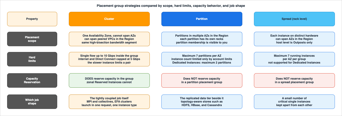
7.2 The constraints that decide the design
| Property | Cluster | Partition | Spread (rack level) |
|---|---|---|---|
| Availability Zone scope | Single Availability Zone; cannot span multiple | Can have partitions in multiple Availability Zones in the same Region | Can span multiple Availability Zones in the same Region |
| Hard size limit | No documented per-group instance cap; bounded by capacity | Maximum seven partitions per Availability Zone; instance count limited only by account limits | Maximum seven running instances per Availability Zone per group |
| Single-flow bandwidth | Up to 10 Gbps inside the group, versus 5 Gbps outside, for enhanced-networking instances | Standard | Standard |
| Internet and Direct Connect | Limited to 5 Gbps | Standard | Standard |
| Dedicated Instances | c7g.16xlarge, m7g.16xlarge, r7g.16xlarge not supported with EFA attached | Maximum two partitions with Dedicated Instances | Not supported |
| Capacity Reservations | Recommended — create an On-Demand Capacity Reservation in the group | Do not reserve capacity in a partition placement group | Do not reserve capacity in a spread placement group |
| VPC scope | Can span peered VPCs in the same Region | Standard | Standard |
The Capacity Reservation row is the one that most often surprises people, and it is documented as a flat statement for both partition and spread: "Capacity Reservations do not reserve capacity in a partition placement group" and "Capacity Reservations do not reserve capacity in a spread placement group." If your capacity strategy assumes a reservation is protecting a partitioned cluster, it is not.
For cluster placement groups the guidance runs the other way: "We recommend that you reserve capacity explicitly in the cluster placement group by creating an On-Demand Capacity Reservation in the cluster placement group. Note that you can't reserve capacity using zonal Reserved Instances, as they can't reserve capacity explicitly in a placement group." The EFA tutorial repeats the same advice: "To ensure that capacity is available as you scale your cluster's instances, you can create a Capacity Reservation for your cluster placement group."
7.3 Launching into a cluster placement group without fighting capacity
Cluster placement groups ask the placement system for a lot of adjacent capacity at once, and AWS's launch recommendations reflect that:- Use a single launch request to launch the number of instances you need in the placement group.
- Use the same instance type for all instances in the placement group.
AWS then explains the failure mode directly: "If you try to add more instances to the placement group later, or if you try to launch more than one instance type in the placement group, you increase your chances of getting an insufficient capacity error." And you can launch multiple instance types into a cluster placement group, but "this reduces the likelihood that the required capacity will be available for your launch to succeed."
There is also a documented recovery move that is not obvious: "If you receive a capacity error when launching an instance in a placement group that already has running instances, stop and start all of the instances in the placement group, and try the launch again. Starting the instances may migrate them to hardware that has capacity for all of the requested instances." That is a disruptive action on a running cluster, so treat it as a maintenance-window operation rather than a routine retry.
One more constraint that affects heterogeneous clusters: "The maximum network throughput speed of traffic between two instances in a cluster placement group is limited by the slower of the two instances." A cluster placement group does not average out a mismatched pair; the smaller instance sets the ceiling for that link.
7.4 Which strategy for a tightly coupled job
For a synchronous training or HPC job, the answer is cluster, for three reasons that stack:- It is a single Availability Zone, which is a hard requirement anyway because EFA traffic cannot cross an Availability Zone.
- It places the instances in the same high-bisection-bandwidth segment, which is exactly what all-to-all collectives consume.
- It is the only one of the three where a Capacity Reservation actually reserves capacity, which matters because the job needs all N nodes or it needs none.
Partition placement groups are for the storage or state tier next to the job — a replicated file system or database where you want replicas on independent racks. Spread is for a handful of critical singletons, and its seven-instances-per-Availability-Zone ceiling rules it out for a compute cluster of any size.
Note the asymmetry this creates with fault isolation. A cluster placement group deliberately concentrates your job; it is the opposite of a blast-radius-reduction pattern. That is the correct trade for a job that cannot survive losing a node anyway, but it is worth being conscious of. If you are designing the surrounding service for containment, my Cell-Based Architecture and Shuffle Sharding on AWS covers the boundaries that do isolate failure — and a tightly coupled job is best modeled as living inside one such boundary, not as spanning several.
Finally: a cluster placement group is not required for EFA. AWS is explicit: "It is not an absolute requirement to launch your EFA-enabled instances into a cluster placement group. However, we do recommend running your EFA-enabled instances in a cluster placement group as it launches the instances into a low-latency group in a single Availability Zone." It is a recommendation with a strong reason behind it, not a prerequisite — which is why forgetting it produces a working but slow cluster rather than an error.
The other half of "all N nodes or none" lives in the scheduler rather than in the placement system: which queue the job waits in, and whether the scheduler will hand out a partial allocation at all. That side is covered in Batch and HPC Job Scheduling on AWS.
8. Instance and Fabric Selection
8.1 Do not hard-code an instance list
AWS publishes a table of EFA-supported instance types, and it changes with every launch. As of 2026-08-04, that table spans four Nitro generations and covers general purpose, compute optimized, memory optimized, storage optimized, accelerated computing, and HPC families — including, in the current Nitro v6 group,m8i, c8i, r8i, c8gn, m9g, g7, g7e, p6-b200, p6-b300, and hpc8a sizes, among many others. I am deliberately not reproducing the full list here: the scope of anything I could write is "what appeared on the AWS page on the date above," and it would be stale within weeks.Query it instead. AWS documents the exact command, and it answers the question for the Region you are actually deploying into, since availability varies by Region:
aws ec2 describe-instance-types \
    --region us-east-1 \
    --filters Name=network-info.efa-supported,Values=true \
    --query "InstanceTypes[*].[InstanceType]" \
    --output text | sort
The same API surface carries the rest of what you need for a selection decision.
NetworkInfo.MaximumNetworkCards tells you how many EFAs the type can carry, since AWS documents that instance types supporting multiple network cards "can be configured with one EFA per network card" while all others support only one EFA per instance. A worked example from the AWS HPC Blog uses this shape of query to filter by vCPU count, architecture, accelerator, and EFA support together, which is the right way to shortlist candidates.For a general approach to checking limits before you design to them, see my AWS Service Quotas Practical Cheat Sheet.
8.2 What actually differentiates the candidates
Once you have the list of EFA-capable types in your Region, four properties separate them:- Nitro generation, because it gates RDMA write and the SRD health metrics (Section 5.3).
- Number of network cards and therefore EFA devices, which sets your aggregate fabric bandwidth ceiling and drives the interface layout of Section 5.2.
- Whether EFA and ENA bandwidth are shared on that type, which determines how much your storage and checkpoint traffic eats into your collective bandwidth.
- Baseline versus "up to" network bandwidth, because a burst-credit-backed figure is not a figure you can design a steady-state collective against.
There is a fifth that is easy to overlook on large multi-socket instances: NUMA locality of the EFA devices. The AWS HPC Blog's analysis of
hpc7a makes the point concretely — the instance has two NUMA domains and the two EFA devices are associated with one NUMA node each, and "Using the network card closest to your MPI process allows for much better performance." If your job binds ranks to cores without also binding them to the nearest fabric device, you are paying a cross-socket hop on every message.8.3 Proximity you can actually measure: the topology APIs
Placement groups tell EC2 what you want. The topology APIs tell you what you got.DescribeInstanceTopology "Describes a tree-based hierarchy that represents the physical host placement of your EC2 instances within an Availability Zone or Local Zone. You can use this information to determine the relative proximity of your EC2 instances within the Amazon Web Services network to support your tightly coupled workloads."The model AWS documents is straightforward: "The AWS network is arranged in a hierarchy of layers. EC2 instances connect into the network at or below the third layer, depending on the instance type. An instance's topology is described by a set of nodes, with one node in each layer of the network." The response lists nodes top-down, the last node is the one the instance connects to, and the reading rule is: "To work out which instances are close to each other, first find common network nodes in the bottom layer. If there are no common network nodes in the bottom layer, then find common network nodes in the upper layers."
AWS states the general rule plainly: "if the network node connected to any two instances is the same, these instances are physically close to each other... Furthermore, the fewer the number of hops between network nodes, the closer the instances are to each other."
aws ec2 describe-instance-topology \
    --region us-west-2 \
    --filters Name=instance-type,Values=trn1n.32xlarge
Response elements per instance are
InstanceId, InstanceType, GroupName, NetworkNodes, CapacityBlockId, ZoneId, and AvailabilityZone. Most instance types return three network nodes; AWS documents p6-b200.48xlarge and p6-b300.48xlarge as returning four.The prerequisites are real and worth checking before you design a scheduler around this:
- Instance types. Supported types are enumerated and are the accelerated, HPC, and Trainium families —
g6eandg7esizes, thehpc6a/hpc6id/hpc7g/hpc7a/hpc8afamily,p3dn/p4d/p4de/p5/p5e/p5en/p6e-gb200/p6-b200/p6-b300, andtrn1/trn1n/trn2/trn2usizes. This is a much narrower list than the EFA-supported list. - State. Instances must be
runningforDescribeInstanceTopology. - Regions. A specific list, not all Regions.
- IAM.
ec2:DescribeInstanceTopology, andec2:DescribeCapacityReservationTopologyfor the companion API.
8.4 Planning before launch, not after
The companion API is the one that changes how you plan.DescribeCapacityReservationTopology works on Capacity Reservations in the pending or active state — that is, before you launch anything. AWS lays out the division of labour directly:| Comparison point | DescribeInstanceTopology | DescribeCapacityReservationTopology |
|---|---|---|
| Usage phase | Post-launch (execution mode) | Pre-launch (planning and management mode) |
| Primary purpose | Optimize workloads on running instances | Capacity planning and Capacity Reservation management (merge, split, assign) before instance launch |
| State required | Instances running | Capacity Reservations pending or active |
| Use cases | Workload optimization, performance tuning, runtime topology analysis | Capacity planning, Capacity Reservation management, pre-launch topology assessment |
AWS gives a worked interpretation: two Capacity Reservations sitting on different layer-ii network nodes means "communication from instances in one Capacity Reservation to instances in the other Capacity Reservation will be inefficient." That is a fact you would much rather learn before you launch 64 accelerated instances than after.
Two operational caveats AWS documents: the Capacity Reservation API shows only a partial node set, since "Visibility of additional nodes requires an instance launch and the DescribeInstanceTopology API"; and the EC2 API is eventually consistent, so calling
DescribeInstanceTopology immediately after launch "might return a null value for capacityBlockId because the data might not have fully propagated across all subsystems."Finally, a note on the capacity mechanism designed for exactly this shape of workload. AWS documents that instances running inside an EC2 Capacity Block "are automatically placed close together inside Amazon EC2 UltraClusters, for low-latency, petabit-scale, non-blocking networking," in cluster sizes from one to 64 instances, and that UltraServers connect multiple instances with a dedicated accelerator interconnect. If your job is on accelerated instances, the placement question and the capacity question are answered by the same construct.
9. The Data Path Around the Job
A tightly coupled job is not only its collectives. Data has to arrive, checkpoints have to leave, and both share the adapters the collectives are using.9.1 Three flows, one set of adapters
| Flow | Pattern | Where it goes |
|---|---|---|
| Training or input data read | Sustained, high aggregate throughput, many readers on the same dataset | Shared file system or object storage, over the ENA path |
| Collective communication | Bursty, latency-sensitive, synchronized across all ranks | Peer instances, over EFA or ENA Express |
| Checkpoint write | Periodic, very large, all ranks at once | Shared file system or object storage, over the ENA path |
The reason this belongs in a networking article rather than a storage one is the sharing. AWS documents for P6-B300 that "Since EFA and ENA traffic share the same underlying resources, bandwidth used by one will reduce the bandwidth that is available to the other." Your checkpoint is not free; it is taken out of the same budget as your all-reduce.
That has a concrete scheduling consequence. A checkpoint that fires while a collective is in flight does not merely queue behind it — it competes for adapter resources and lengthens the tail of that collective, which is the one thing a synchronized job cannot absorb. Aligning checkpoint writes to a step boundary, and staggering them across ranks where the format allows, is a networking decision as much as a storage one.
This article stops at the bandwidth. Where those checkpoints are placed, and how far a failure sends the job back depending on which layer still holds the state, is the subject of my Distributed Training Resilience on AWS.
Inference adds a fourth flow of the same shape. When the prefill phase and the decode phase of LLM serving run on separate pools, the key-value cache computed by the prefill side has to reach the decode side over this same fabric, and it competes for the same adapter budget as everything else. Disaggregated Prefill and Decode for LLM Serving on AWS covers that transfer and the ways it degrades.
9.2 Where the data comes from
For the shared file system that feeds a training job, the AWS answer in this space is Amazon FSx for Lustre, and the pairing with EFA-enabled instances is long-standing in AWS's own material. Choosing among the FSx file systems is a separate decision with its own trade-offs, and I cover it in my Amazon FSx Family Decision Guide. Where the shared file system is Amazon EFS instead, the ceilings that decide what it will sustain sit both on the file system as a whole and on each client separately, and I cover those in my Amazon EFS Performance Engineering.The alternative is instance-local storage — using an instance type with local NVMe so that the hot dataset never crosses the network at all. That removes read traffic from the adapters entirely, in exchange for having to stage the data onto every node and losing it when the node goes away. The block-storage side of that comparison, including where io2 Block Express fits, is in my Amazon EBS Performance Engineering guide — which is also, as Section 4.3 noted, the third place SRD shows up in EC2.
9.3 What does not belong on the fabric
Because EFA traffic is not routable and cannot leave the Availability Zone or the VPC, everything that does leave — object storage access, orchestration, metrics, package installs, cross-Region replication — travels over the ENA side. That is the correct arrangement, and it is worth being deliberate about it:- Keep the ENA path's egress design separate from the fabric design. Interface and gateway endpoints keep storage and API traffic inside your VPC boundary rather than out through a gateway; see my AWS PrivateLink and VPC Endpoints Complete Guide.
- Remember the cluster placement group ceiling from Section 7.2: internet and Direct Connect traffic is limited to 5 Gbps for a cluster placement group. If your data ingest comes from on-premises over Direct Connect, that number, not your instance's headline bandwidth, is what you are designing against. Choosing among the connectivity options is covered in my AWS VPC Connectivity Decision Guide.
10. Observability for the Fabric
The distinguishing property of fabric problems is that they do not look like errors. The job runs. It is just slower than it should be, and the slowness moves around.10.1 EFA driver metrics
The EFA driver publishes counters to the instance in real time. AWS describes their purpose as troubleshooting application performance and networking issues, choosing the right cluster size for a workload, and planning scaling activities.The traffic counters —
tx_bytes, rx_bytes, tx_pkts, rx_pkts, rx_drops, send_bytes, recv_bytes, send_wrs, recv_wrs — and the RDMA counters — rdma_write_wrs, rdma_read_wrs, rdma_write_bytes, rdma_read_bytes, rdma_write_wr_err, rdma_read_wr_err, rdma_read_resp_bytes, rdma_write_recv_bytes — are available on all instance types that support EFA.The five that tell you the fabric is unhealthy are available only on Nitro v4 and later:
| Metric | What it means | Why you care |
|---|---|---|
retrans_bytes | Number of EFA SRD bytes retransmitted | Baseline loss level on your paths |
retrans_pkts | Number of EFA SRD packets retransmitted | Same, per packet |
retrans_timeout_events | "The number of times EFA SRD traffic timed out and resulted in a network path change" | A path was bad enough that SRD abandoned it — the closest thing to a direct signal of a problem path |
impaired_remote_conn_events | "The number of times EFA SRD connections entered an impaired state, resulting in a reduced throughput rate limit" | A peer connection is being rate-limited, which will show up as one slow rank |
unresponsive_remote_events | "The number of times an EFA SRD remote connection was unresponsive" | A specific peer stopped answering |
The last two are the ones to alarm on for a synchronized job, because they identify which peer relationship is degraded — and in a collective, one degraded relationship sets the step time for everyone.
AWS documents two ways to read them. The
rdma tool:rdma -p statistic showor the sysfs counters directly:
more /sys/class/infiniband/device_number/ports/port_number/hw_counters/* | catBoth are cumulative since instance launch or the last driver reset, so what you want is the delta over a job step or an interval, not the absolute value.
10.2 ENA Express metrics
For ENA Express the driver exposes a small set throughethtool, and AWS notes that driver version 2.8 or higher is required to produce them:ethtool -S eth0 | grep ena_srdNIC statistics:
ena_srd_mode: 1
ena_srd_tx_pkts: 0
ena_srd_eligible_tx_pkts: 0
ena_srd_rx_pkts: 0
ena_srd_resource_utilization: 0ena_srd_mode is the configuration readout, and AWS documents its values:| Value | Meaning |
|---|---|
0 | ENA Express off, UDP off |
1 | ENA Express on, UDP off |
2 | ENA Express off, UDP on |
3 | ENA Express on, UDP on |
Value
2 is worth a second look — AWS notes it occurs "when ENA Express was originally enabled, and UDP was configured to use it. The prior value is retained for UDP traffic."The diagnostic that matters most is the pair
ena_srd_eligible_tx_pkts and ena_srd_tx_pkts. AWS frames the intended uses as identifying "where there are potential issues that prevent eligible outgoing packets from using SRD" and calculating "the percentage of outgoing traffic that uses SRD for the instance." A large eligible count with a small actual count is the signature of the silent fallback described in Section 6.3 — the packets could have used SRD, and did not. That is your alarm.ena_srd_resource_utilization is the capacity signal: AWS lists "Evaluate your resources to ensure that they have sufficient capacity to establish more SRD connections" as one of the intended uses.10.3 Instance-level allowance metrics
The ENA counters from Section 3.2 are the layer beneath both features, and for a fabric investigation they answer the question "is the instance itself throttling before the network is even involved?" The CloudWatch agent can import ENA network performance metrics from version 1.246396.0 and later, prependingethtool_ to each name on Linux instances, so you can put bw_out_allowance_exceeded and pps_allowance_exceeded on the same dashboard as everything else. For the broader instrumentation architecture that dashboard belongs in, see my AWS Observability Architecture Guide.10.4 The flow-log surprise
This one deserves its own subsection because it derails investigations. You can create a VPC flow log for an EFA the same way you create one for any elastic network interface — but the records do not look like the ones you are used to. AWS documents that "In the flow log entries, EFA traffic is identified by thesrcAddress and destAddress, which are both formatted as MAC addresses," and the example record shows - in the source port, destination port, and protocol columns.So: no IP addresses, no ports, no protocol. If your incident runbook says "check the flow logs for the training subnet," it will not answer any question you have about EFA traffic. The EFA driver counters in Section 10.1, not flow logs, are the instrument for that traffic. Flow logs remain useful for the ENA side — the data reads, the checkpoint writes, the orchestration.
10.5 A triage order
When a tightly coupled job is slower than expected, this order resolves it fastest, because each step is quick and rules out a whole class:- Is EFA even in use? Run
fi_info -p efa -t FI_EP_RDMon the nodes. If it returns nothing, stop here — the rest is irrelevant. - Is the library using the EFA provider? Confirm from the communication library's own logs that it selected the EFA provider rather than a sockets fallback.
- Is the instance being throttled before the network? Check
bw_*_allowance_exceeded,pps_allowance_exceeded, andconntrack_allowance_exceeded. Remember microbursts: low averages do not clear the instance. - Is the fabric losing packets or changing paths? Take deltas of
retrans_pktsandretrans_timeout_eventsacross a job step. - Is one peer relationship degraded? Check
impaired_remote_conn_eventsandunresponsive_remote_events, and identify the node. - Are the nodes actually near each other? Call
DescribeInstanceTopologyand compare network node sets. A rank whose bottom-layer node is shared with nobody is a candidate for the straggler. - Is the process bound to the nearest fabric device? On multi-socket instances with more than one EFA, confirm rank-to-device affinity (Section 8.2).
Steps 1 and 2 find the majority of real cases, and they take a minute.
11. Failure Modes and Anti-Patterns
11.1 EFA is enabled, and unused
The most common failure by a wide margin. The launch template saysInterfaceType=efa, the console shows the interface, the job runs, the results are correct — and every message went over TCP because the EFA software stack was not installed in the AMI, or the installed Libfabric was too old for the library in the container image, or the library silently selected a sockets provider.There is no error for this. The check is
fi_info -p efa -t FI_EP_RDM on every node, wired into cluster bring-up as a gate, plus confirming the provider selection in the communication library's logs. If your automation cannot fail a job for this, it will eventually run a long, expensive job at TCP speed.11.2 The security group is self-referencing in one direction
AWS's requirement is that the security group "allows all inbound and outbound traffic to and from the security group itself," and the documented procedure adds two rules — one inbound, one outbound — each pointing at the group's own ID.The half-configured version is very hard to spot because ordinary connectivity is unaffected: SSH works, health checks pass, the scheduler sees the nodes. Only the EFA traffic fails. If you template your security groups, assert on both directions.
11.3 A tightly coupled job without a cluster placement group
Because a cluster placement group is a recommendation rather than a requirement, omitting it produces no error at all. You get instances scattered across the Availability Zone, more hops between them, and — for anything falling back to TCP — a 5 Gbps single-flow ceiling instead of 10 Gbps. The job runs. It scales badly, and the badness is attributed to the model, the framework, or the batch size.11.4 Choosing an instance type that cannot do what you assumed
Three distinct versions of this:- The type does not support EFA at all, so the launch fails or the interface type is rejected.
- The type supports EFA on an older Nitro generation, so you get EFA without RDMA write and without the five SRD health metrics — meaning you have also lost your primary diagnostic (Section 5.3).
- The type supports EFA but is excluded from a specific combination: Dedicated Instances and Dedicated Hosts are not supported for
c7g.16xlarge,m7g.16xlarge, andr7g.16xlargewhen an EFA is attached, and EFA traffic between P4d, P4de, and DL1 instances and other instance types is not supported.
Validate against the API (Section 8.1), not against a table you copied into a runbook.
11.5 Assuming EFA reaches across an Availability Zone
EFA traffic cannot cross Availability Zones or VPCs, and it is not routable. A multi-Availability-Zone design for a single tightly coupled job is not a resilience improvement — it is a configuration that will not carry the job's traffic on the fabric at all.The trap here in 2026 is transferring the mental model from ENA Express, which as of May 11, 2026 does work across Availability Zones within a Region. The two features made opposite choices on this axis, and the change to one of them does not apply to the other.
11.6 Half-configured ENA Express
ENA Express requires both ends. AWS documents the mixed case: enable it on one instance with UDP, on the other without UDP, and TCP uses ENA Express while UDP silently reverts to standard ENA transmission. Because settings attach to the attachment rather than to the interface, an interface that is detached and reattached loses them, and an autoscaled replacement node launched from a template that lacks the setting joins the fleet as a non-participant.The detector is in the metrics:
ena_srd_eligible_tx_pkts climbing while ena_srd_tx_pkts does not.11.7 Applying EFA to a workload that does not need it
EFA is a real amount of operational surface: an AMI with a specific driver stack, a security group with self-referencing rules on both directions, a placement constraint that pins you to one Availability Zone, a narrower instance-type list, and a launch-time-only attachment decision.If the workload is a queue-driven fleet, an inference service behind a load balancer, or a batch pipeline where workers do not talk to each other, none of that buys anything. Section 2's test is the one to apply: is there a synchronization point where progress depends on messages from other nodes within the same iteration? If not, the standard ENA path is the correct answer, and ENA Express is the correct answer for the narrower case of a single flow that needs more than 5 Gbps.
11.8 Making an EFA-only interface the primary interface
AWS states it twice in the launch guidance: "You can't use an EFA-only network interface as the primary network interface." An EFA-only interface has no IP networking, cannot be assigned IPv4 or IPv6 addresses, and provides nothing the operating system can boot a network stack on. The primary interface (network card index0, device index 0) must be an ENA interface.11.9 Forgetting ptrace protection on Ubuntu
AWS documents disabling ptrace protection "so that Libfabric works properly," and notes that Ubuntu distributions enable it by default. If your AMI pipeline builds on Ubuntu and the step is missing, you have a build that installs cleanly and behaves badly.11.10 Attaching EFA to a running instance
You cannot. AWS documents that an EFA can be attached to a supported instance in thestopped state and not in the running state. Any remediation plan that involves adding EFA to a live cluster requires a stop, and any capacity assumption you had about those instances is re-evaluated when you start them again — which, per Section 7.3, is exactly when a cluster placement group can hand you an insufficient-capacity error.11.11 Expecting ENA Express to improve an idle network
AWS documents a possible "slight increase in median packet latency (tens of microseconds)" when traffic is light, and advises that for high packets-per-second workloads optimizing for latency during uncongested periods, enhanced networking "might be a better fit." Enabling ENA Express fleet-wide as a default, without asking whether the workload's problem is the tail under load, can make a latency-sensitive service marginally worse.12. Frequently Asked Questions
Do I need EFA, or is ENA Express enough?
Ask what your communication library speaks. If the application uses MPI, NCCL, NIXL, or the Neuron SDK — that is, if it can reach Libfabric — EFA is the fabric built for it. If the application uses ordinary TCP or UDP sockets and its problem is single-flow throughput or tail latency under load, ENA Express gives it SRD without a code change. They address different applications, so the choice is usually determined before you start comparing them.Can EFA traffic cross an Availability Zone?
No. AWS documents that EFA traffic cannot cross Availability Zones or VPCs, and that it is not routable. This applies specifically to traffic through the EFA device; normal IP traffic from the ENA device of an EFA-with-ENA interface behaves like any other VPC traffic. This is the reason a cluster placement group — which is single-Availability-Zone by definition — is the natural placement for an EFA cluster.Can ENA Express cross an Availability Zone?
Yes, as of the announcement on May 11, 2026, within the same Region — and AWS documents up to 25 Gbps single-flow bandwidth for that case. Three qualifications: the documented tail-latency benefit is stated for instances in the same Availability Zone; cross-Availability-Zone support is not available in South America (São Paulo), Middle East (Bahrain), or Middle East (UAE); and ENA Express traffic cannot be sent in a Local Zone.Is a cluster placement group required for EFA?
No. AWS says explicitly that it is "not an absolute requirement," but recommends it "as it launches the instances into a low-latency group in a single Availability Zone." Because it is not required, omitting it produces no error — just a cluster that is more spread out than you intended. Treat it as required in your own templates.How do I know EFA is actually being used and not silently falling back to TCP?
Runfi_info -p efa -t FI_EP_RDM on each node; it should return the Libfabric EFA provider with a FI_EP_RDM endpoint. Then confirm from your communication library's logs that it selected the EFA provider. Do both as a gate in cluster bring-up rather than as a manual step, because nothing else in the system will tell you.Why does my VPC flow log show MAC addresses instead of IP addresses?
Because that is how EFA traffic appears. AWS documents that in flow log entries, EFA traffic is identified bysrcAddress and destAddress formatted as MAC addresses, with no source port, destination port, or protocol. Flow logs are the wrong instrument for EFA traffic; use the EFA driver counters instead. They remain the right instrument for the ENA-side traffic on the same instances.Which metrics tell me the fabric, and not my code, is the problem?
On Nitro v4 and later instance types:retrans_pkts and retrans_bytes for loss, retrans_timeout_events for SRD abandoning a path, and impaired_remote_conn_events plus unresponsive_remote_events for a specific peer relationship degrading. Those last two are the ones to alarm on for a synchronized job, because a single degraded peer sets the step time for every rank. Take deltas across a job step; the counters are cumulative since launch or driver reset.Can I add EFA to a cluster that is already running?
No. An EFA can be attached to a supported instance in thestopped state, not the running state. Plan it at launch. If you must retrofit, expect a stop and start of the whole placement group, and re-check capacity — AWS notes that starting instances may migrate them to hardware with capacity, but also that a start can fail if capacity is not there.Does a Capacity Reservation protect my placement group?
Only for cluster placement groups. AWS documents that Capacity Reservations do not reserve capacity in a partition placement group or in a spread placement group. For cluster placement groups, AWS recommends creating an On-Demand Capacity Reservation in the group, and notes you cannot reserve capacity there using zonal Reserved Instances.What does SRD actually change, in one sentence?
It gives up in-order packet delivery so it can spray a message across many network paths at once and avoid head-of-line blocking, then restores ordering above the wire where the application needs it — which is why AWS describes the benefit primarily as a tail-latency improvement rather than a bandwidth one.13. Summary
The design question this article answers is not "should I turn on EFA." It is "what does my workload's communication pattern require, and what does the AWS network offer for it."- Classify the workload first. A synchronization point where progress depends on other nodes within the same iteration is what makes tail latency, rather than bandwidth, the property that limits scaling. Without one, most of this article does not apply (Section 2).
- SRD is one transport with two doors. EFA hands it to the application through Libfabric with the kernel bypassed; ENA Express slides it under ordinary TCP and UDP. AWS attributes a roughly tenfold p99 tail-latency improvement to the decision to give up in-order delivery — quoted as AWS's claim about AWS's own network, not as a measurement (Sections 4, 5, 6).
- The two doors reach different places. EFA traffic cannot cross an Availability Zone or a VPC and is not routable. ENA Express works across Availability Zones within a Region as of May 11, 2026, excluding three Regions and Local Zones. Do not transfer one feature's properties to the other (Sections 5.5, 6.2).
- Cluster placement group for the job; partition for the replicated tier. Cluster is single-Availability-Zone with a high-bisection-bandwidth segment and a 10 Gbps single-flow limit instead of 5 Gbps — and it is the only one of the three where a Capacity Reservation actually reserves capacity. Launch in one request, with one instance type (Section 7).
- Select instances from the API, not from a table. Filter with
network-info.efa-supported, then differentiate by Nitro generation (which gates RDMA write and the SRD health metrics), network card count, whether EFA and ENA share bandwidth, and NUMA locality of the devices (Section 8). - Verify proximity rather than assuming it.
DescribeCapacityReservationTopologybefore launch andDescribeInstanceTopologyafter; instances sharing a bottom-layer network node are close, and fewer hops to a common node means closer (Section 8.3, 8.4). - Budget the whole data path. EFA and ENA traffic share underlying resources on the same instance, so checkpoints and dataset reads come out of the same budget as collectives, and a checkpoint fired mid-collective lengthens exactly the tail you were trying to shorten (Section 9).
- Instrument the fabric specifically.
fi_infoas a bring-up gate, the five Nitro v4+ SRD counters as the health signal,ena_srd_eligible_tx_pktsversusena_srd_tx_pktsas the fallback detector — and do not expect VPC flow logs to help, because EFA traffic appears there as MAC addresses with no ports or protocol (Section 10).
The single most valuable habit from all of this is small: make the cluster prove it is using the fabric before it starts doing work. Every other failure in Section 11 is expensive because it is silent, and one command at bring-up converts most of them from a slow job into a failed launch.
For the adjacent decisions this article deliberately delegates: define the networking terms used above with my AWS Networking Glossary, trace the Nitro generations that gate these capabilities in my AWS Custom Silicon History and Timeline and the families that carry them in my Amazon EC2 Instance Types History and Timeline, work out where an Availability Zone boundary sits in my AWS History and Timeline regarding AWS Global Infrastructure, design the containment boundary around the job in my Cell-Based Architecture and Shuffle Sharding on AWS, and contrast all of it with the loosely coupled case in my Large-Scale Batch Generative AI Pipeline on AWS.
14. References
- Amazon EC2 User Guide - Elastic Fabric Adapter for AI/ML and HPC workloads on Amazon EC2
- Amazon EC2 User Guide - Get started with EFA and MPI for HPC workloads on Amazon EC2
- Amazon EC2 User Guide - Get started with EFA and NCCL for ML workloads on Amazon EC2
- Amazon EC2 User Guide - Get started with EFA and NIXL for inference workloads on Amazon EC2
- Amazon EC2 User Guide - Create and attach an Elastic Fabric Adapter to an Amazon EC2 instance
- Amazon EC2 User Guide - Maximize network bandwidth on Amazon EC2 instances with multiple network cards
- Amazon EC2 User Guide - Monitor an Elastic Fabric Adapter on Amazon EC2
- Amazon EC2 User Guide - Improve network performance between EC2 instances with ENA Express
- Amazon EC2 User Guide - Monitor network performance for ENA settings on your EC2 instance
- Amazon EC2 User Guide - Amazon EC2 instance network bandwidth
- Amazon EC2 User Guide - Nitro system considerations for performance tuning
- Amazon EC2 User Guide - Placement strategies for your placement groups
- Amazon EC2 User Guide - How Amazon EC2 topology works
- Amazon EC2 User Guide - Prerequisites for Amazon EC2 topology
- Amazon EC2 User Guide - Examples for Amazon EC2 instance topology
- Amazon EC2 FAQs - Elastic Fabric Adapter, ENA Express, and Capacity Blocks for ML
- AWS HPC FAQs
- AWS HPC Blog - In the search for performance, there's more than one way to build a network
- AWS HPC Blog - Second generation EFA: improving HPC and ML application performance in the cloud
- AWS HPC Blog - Optimizing MPI application performance on hpc7a by effectively using both EFA devices
- AWS HPC Blog - Support for Instance Allocation Flexibility in AWS ParallelCluster 3.3
- AWS News Blog - New: ENA Express - Improved Network Latency and Per-Flow Performance on EC2
- AWS What's New - ENA Express for Amazon EC2 instances now supports traffic between Availability Zones
- AWS Networking and Content Delivery Blog - Using ENA Express to improve workload performance on AWS
- AWS Networking and Content Delivery Blog - Amazon EC2 instance-level network performance metrics uncover new insights
- AWS Networking and Content Delivery Blog - Improving Performance on AWS and Hybrid Networks
- AWS Compute Blog - Using partition placement groups for large distributed and replicated workloads in Amazon EC2
- AWS Well-Architected Performance Efficiency Pillar - PERF04-BP05 Choose network protocols to improve performance
- Amazon CloudWatch User Guide - Collect network performance metrics
- AWS re:Post - Why does my Amazon EC2 instance exceed its network limits when my average utilization is low?
References:
Tech Blog with curated related content
Written by Hidekazu Konishi