Sharing One GPU on Amazon EKS - Where the Split Is Declared, Where It Is Enforced, and What Each Method Leaves Shared
First Published:
Last Updated:
Developers are competing for access to GPU nodes, and someone is always waiting whenever a notebook is launched.
There is a requirement to support multi-tenancy and prevent other tenants from consuming excessive memory.
It appears that sharing a single GPU across multiple Pods can resolve all three of these issues. And in fact, Amazon EKS provides mechanisms for doing so. However, the challenge lies beyond that. There is not just one way to split the GPU; each method provides a different level of isolation from neighboring Pods.
Put the axis first. The location where you declare the split and the area where isolation is actually enforced are not the same. A single line in a Pod's specification simply states how many GPU resources it requests; it does not guarantee that neighboring Pods will not consume its memory. What sets the actual scope is the sharing mechanism enabled on the node itself. And you cannot determine which mechanism is active just by looking at the Pod's specification.
This article focuses specifically on solutions within a single device. It covers three methods, one that splits by time, one that runs processes together, and one that splits the hardware, and what each of them makes dedicated and what it leaves shared. It also covers which hardware each method can run on, and what decides whether it works on Amazon EKS.
The technical information presented in this article is based on the Amazon EKS user guide (specifically the "Manage hardware devices on Amazon EKS," "Manage NVIDIA GPUs on Amazon EKS," "Use the NVIDIA DRA driver or device plugin on Amazon EKS," "Use multi-instance GPUs (MIG) with NVIDIA GPUs on Amazon EKS," and "Use time-slicing with NVIDIA GPUs on Amazon EKS" pages), as well as the Amazon EKS best practices guide's "Compute and Autoscaling" section, as of September 8, 2026. This area moves with each hardware generation and each driver release. The supported instance types, profiles, and feature stability should always be verified at the time of reading. This article does not discuss pricing and does not include any performance figures measured in-house.
Table of Contents
- 1. One Line, Four Different Meanings
- 2. Time-Slicing Splits Turns, Not Memory
- 3. Sharing Removes the Instrument That Would Show You the Result
- 4. MPS Sits in Between, and Cannot Share a GPU with Time-Slicing
- 5. MIG Splits the Hardware
- 6. The Three Do Not Sit at the Same Level
- 7. What Choosing MIG Takes Away
- 8. Each Split Against What It Actually Protects
- 9. Finding Out Which Configuration You Are Actually On
- 10. Which Hardware Can Be Split at All
- 11. How You Supply Nodes Decides What Works
- 12. The Alpha Label Is on the Driver, Not on Kubernetes
- 13. Where the Primary Sources Disagree
- 14. Failure Modes and Anti-Patterns
- 15. Frequently Asked Questions
- 16. Summary
- 17. References
1. One Line, Four Different Meanings
1.1 Who This Article Is For
This article assumes the perspective of someone already operating GPU nodes within Amazon EKS. You have a cluster, nodes with GPU instances, and development, training, or inference workloads running on them. You are likely experiencing low GPU utilization, or facing a need to share a single GPU across multiple users.This article does not provide a universal solution for choosing the best approach. Instead, its purpose is to help you verify what guarantees your chosen configuration gives a neighboring Pod, and what it does not. Only by understanding the scope of these guarantees can you determine whether your configuration is suitable for a multi-tenant environment.
1.2 What Slice Means in This Article
Within this area, there are two kinds of "slice," and they are easy to confuse. One refers to the division of time, and the other refers to the division of processing units. Using the same term for both obscures a key distinction that this article aims to clarify: dividing time does not necessarily involve dividing processing units. Therefore, this article consistently uses different terms for each.- Time slice refers to a sequence of operations performed on a single GPU. This is what time-slicing creates.
- Compute slice refers to the physical division of the GPU's compute units themselves. The numbers that appear in MIG profiles represent this.
These two are entirely independent; the existence of one does not necessitate the existence of the other. Creating more time slices does not create a single additional compute slice. That single sentence is close to the whole of what this article says.
For the same reason, terms written in code spans, such as
nvidia.com/gpu, refer to the names of Kubernetes extended resources, while the term "GPU" used in its plain form refers to the physical device itself.1.3 The Fourth Unit
This site already contains articles dealing with device allocation in Amazon EKS, and within those articles, the term "unit" is used three times, each with a distinct meaning. Gang Scheduling and Dynamic Resource Allocation on Amazon EKS differentiates between the units it handles and those it does not.The unit this article allocates and the unit that article recovers are not the same unit.
The unit that gets isolated is a third one again: Workload Isolation Levels on Amazon EKS
asks what may share a node and a kernel once the allocation has been made.These units are categorized as: units to be secured, units to be recovered, and units to be isolated. This article addresses a fourth type of unit: a division within a single device. This fourth unit does not overlap with any of the previous three.
| Unit | Question | Article Containing Information |
|---|---|---|
| Unit to be Secured | How many units are secured as a group, and through which path are devices requested? | Gang Scheduling and Dynamic Resource Allocation on Amazon EKS |
| Unit to be Recovered | How far back is recovery possible when a failure occurs? | Distributed Training Resilience on AWS |
| Unit to be Isolated | After allocation, what can share the node and kernel? | Workload Isolation Levels on Amazon EKS |
| Division Unit | Where is the division made within a single device, and what does that division prevent? | This Article |
The boundaries are drawn concretely below.
This article does not discuss the selection of paths. It does not detail which path—whether through the NVIDIA DRA driver or the NVIDIA device plugin—is chosen for device requests, nor what determines that choice. Section 8 of Gang Scheduling and Dynamic Resource Allocation on Amazon EKS describes how the same branching logic applies across three different device types. Section 9 of the same article presents a table detailing the stability of Kubernetes-side feature gates. This article only addresses the constraints applied to the division side, depending on the chosen path.
This article also does not discuss sharing between nodes and the kernel. Workload Isolation Levels on Amazon EKS covers configurations that provide different kernels on a per-namespace, RBAC, Pod Security Standards, and user namespace basis, as well as configurations that provide a different kernel for each Pod. This article focuses solely on the internal division within a single GPU.
The selection of accelerators and the configuration of Karpenter consolidation will not be detailed here. Decisions regarding whether to use GPUs or Neurons, and how to shape single-Pod inference serving belong to Self-Managed LLM Inference on Amazon EKS. Disaggregated Prefill and Decode for LLM Serving on AWS holds the internal design of distributed inference and the KV transfer.
1.4 The Same Line Means Four Different Things
Start from the concrete entry point. You have seen this line in the spec of a Pod that uses a GPU.resources:
limits:
nvidia.com/gpu: 1What this single line actually passes depends on the configuration on the node, and it can change in four different ways. Crucially, the spec side is the same string in all four cases.
| Node Configuration | What this Line Actually Passes | Scope Protected from Neighboring Pods |
|---|---|---|
| No Shared Configuration | One physical GPU | Everything, as it is exclusively allocated. |
| Advertising four slots using time-slicing | One of the four time slices | Neither memory nor compute is protected. |
| MIG single strategy | One MIG instance, cut in hardware | Memory, compute, and fault |
| Requesting fractions with the KAI Scheduler | limits remain at one. The fraction information is located in the annotation. | Only as far as the scheduler agrees. |
Rows two and three come out as the same string because both features are used with settings that leave the resource name alone. Time-slicing has a configuration option to change the advertised resource name, and the Amazon EKS user guide lists using the unchanged value as the recommended approach. As long as you follow the recommendation, the Pod will continue to request
nvidia.com/gpu. The same applies to MIG's single strategy.The device plugin advertises each instance as the nvidia.com/gpu resource, and Pods request
nvidia.com/gpu: 1 as they would for a dedicated GPU. Existing manifests do not change.The fact that existing manifests remain unchanged is an advantage in terms of ease of migration. However, it also means that reading the manifest does not necessarily tell you which configuration you are currently using.
Regarding the default values for these configurations, the Amazon EKS user guide does not explicitly state them, instead deferring to the NVIDIA device plugin documentation. It is important to distinguish between the recommended and default values to avoid confusion.
The fourth row is even further apart. The Amazon EKS best practices guide identifies NVIDIA KAI Scheduler as the component responsible for fractional GPU allocation.
The NVIDIA KAI Scheduler, part of the Run:ai platform, enables this by allowing pods to request
fractional GPU resources.
The examples in this guide show that Pods are requesting 0.5 using the
gpu-fraction annotation, while their limits specify nvidia.com/gpu: 1. The fraction lives in the annotation the scheduler reads, while Kubernetes still counts the resource as one. This demonstrates a key point of this article: the declaration of the fraction and the location where that declaration is enforced exist separately, and the two sit inside one manifest.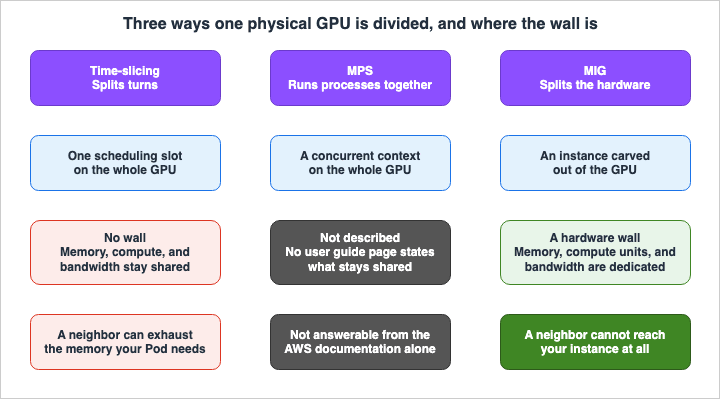
2. Time-Slicing Splits Turns, Not Memory
2.1 What Actually Happens
Time-slicing is a configuration that allows the NVIDIA device plugin or NVIDIA DRA driver to advertise multiple schedulable slots per GPU on a single physical GPU. The Kubernetes scheduler can then place multiple Pods on the same GPU, with the CUDA scheduler on the GPU side performing time-slicing to manage the workload.So the number of GPUs Kubernetes sees goes up. For example, on a node with 8 physical GPUs, if each GPU advertises 4 slots, the node will report 32 GPUs. Physically, however, there are still only 8.
The Amazon EKS user guide succinctly states what this approach doesn't provide. This is the most important quote in this article.
Time-slicing does not offer memory or compute isolation between Pods that share a GPU.Pay close attention to the "or" in "memory or compute." This applies to both memory and compute; it is not a situation where only one is protected. The Considerations section on the same page elaborates on this in two points. Regarding memory, it notes that because Pods share the GPU's memory, one Pod could potentially consume memory needed by another, leading to out-of-memory errors. Regarding compute, the GPU scheduler allocates resources on a best-effort basis and does not guarantee proportional allocation to each Pod.
2.2 What It Suits, and What It Does Not
The user guide describes conditions from both perspectives. It lists conditions directly, without summarizing.Suitable Use Cases:
- GPU utilization is consistently low. An example is inference services that are sensitive to latency and spend time idle between requests.
- Multiple developers are sharing a single GPU node for notebooks and development work.
- The node is using GPU instance types that do not support MIG. Examples include the
g5,g6, andg6efamilies. - The system can tolerate occasional slowdowns for a particular Pod due to high activity on another Pod on the same GPU.
Use Cases Where Alternative Approaches Should Be Considered:
- Memory isolation is required. In this case, using MIG is explicitly recommended.
- Predictable latency and service quality are required for each Pod.
- You run training workloads. Time-slicing adds context switching and lowers training efficiency, and jobs delayed by other Pods may need to be restarted from the most recent checkpoint.
The fourth suitable condition and the second unsuitable condition describe the same thing from opposite sides. Choosing time-slicing is almost equivalent to accepting occasional slowdowns. Whether or not this is acceptable depends on the latency guarantees the service makes externally.
2.3 Requesting Two Slots Does Not Give You Twice the Compute
The device plugin path has one setting that is easy to get wrong. While the device plugin advertises a fixed number of slots per GPU, requesting two or more slots for a single Pod will not result in additional processing power.The user guide lists recommended settings to prevent this, along with suggested values.
Rejects Pods that request more than one time-sliced slot. A Pod that requests more than one slot
does not receive proportional compute. Enable this setting to prevent a common misconfiguration.
Enabling this setting will reject Pods that request two or more slots. If a request is granted, the Pod will continue to operate with only the original number of resources, despite the expectation of doubling them. From the Pod's perspective, the system appears to be functioning normally.
The name of this setting key varies depending on the AMI. The user guide explicitly states that the field names differ between Bottlerocket and AL2023, using
fail-requests-greater-than-one in Bottlerocket and failRequestsGreaterThanOne in AL2023. Searching for one name will not yield results when looking for the other.Regarding the number of slots themselves, the user guide suggests a range of 2 to 8 as a recommended value for the device plugin path. While increasing this value allows for more sharing, it may also increase the potential for conflicts between Pods. This recommendation is not a hard limit. There is no mechanism to reject larger values; rather, it is provided as a guideline for making a choice.
2.4 There Are Three Places to Write the Configuration
Where you write the time-slicing configuration depends on the combination of the path and AMI, resulting in three different options. Despite performing the same function, the configuration name and location do not match.| Path and AMI | Where the Configuration Goes | What Sets the Granularity |
|---|---|---|
| Device Plugin and AL2023 | A ConfigMap, referenced from the Helm values | replicas |
| Device Plugin and Bottlerocket | The node user data. The AMI ships the device plugin | replicas |
| DRA Driver | The GpuConfig in a ResourceClaimTemplate | interval, not a slot count |
Only the third option operates differently. While the device plugin path determines the number of slots, the DRA driver path specifies the length of the CUDA time slice. There are four available values: using the driver's default interval, a shorter interval, a medium interval, and a longer duration for each sequence.
This difference reflects a different level of control over the granularity of sharing. Setting the number of slots to 4 is an operation that changes the number of resources the node advertises. Changing the
interval is an operation that modifies the frequency of switching. The former is visible to the scheduler, while the latter is not.When using the DRA driver with Bottlerocket, there is one additional consideration. The DRA driver cannot coexist on the same node as the NVIDIA device plugin. The NVIDIA variant of Bottlerocket includes the device plugin and enables it by default, so you must explicitly disable it in the node's user data. This setting is available from Bottlerocket 1.63.0 and later; earlier versions do not allow disabling the built-in device plugin.
3. Sharing Removes the Instrument That Would Show You the Result
Previously, the solution seemed straightforward. Simply monitor the memory usage of the shared Pod, identify any Pods experiencing slowdowns, and adjust the number of slots.However, that monitoring becomes ineffective the moment time-slicing is enabled.
3.1 Per-Container Metrics Stop Being Attributable
The Amazon EKS user guide lists this under "Considerations," point number four.NVIDIA Data Center GPU Manager (DCGM) cannot attribute metrics to individual containers when
time-slicing is active. GPU-level metrics remain available, but you cannot identify which Pod
consumed a given amount of GPU resources.Metrics related to GPUs will remain available. You will still be able to see utilization and memory usage. What will no longer be visible is attribution. You can see that a single GPU's memory is 90% full, but you will not be able to determine which of the four Pods is consuming that memory.
The problem arises because the impact of time-slicing is difficult to pinpoint. When one Pod consumes memory that belongs to another, the affected Pod will crash due to an out-of-memory error. It is impossible to determine which Pod was the cause using the GPU-level metrics.
3.2 The Scaling Side Holds a Different Number
Another discrepancy exists in how aggregations are handled. Even for GPUs where time-slicing is enabled, Karpenter counts eachnvidia.com/gpu request as a single physical GPU.Karpenter counts each nvidia.com/gpu request as a physical GPU even when time-slicing is enabled
on the GPU.In other words, the device plugin might advertise 32 slots for a node, while Karpenter calculates it as only 8 GPUs. If the intention of enabling sharing was to increase density, then the scaling side may not be understanding that goal. The user guide cites Karpenter issue #2140 as the rationale for this behavior.
3.3 Configuration Changes Are Not Picked Up
Third, there is an operational pitfall. The NVIDIA device plugin does not monitor changes to theConfigMap for time-slicing. Even if you change the number of slots, the changes will not be reflected until you restart the device plugin's Pod.3.4 Running Both Advertises the Same Device Twice, Silently
Beyond simply sharing resources, there is another potential issue with a similar nature. You must not run both the DRA driver and a device plugin on the same node simultaneously. The user guide explicitly details the consequences of doing so.When using the NVIDIA DRA driver for GPU device management, do not deploy it alongside the NVIDIA
device plugin on the same node. Doing so can cause silent oversubscription of the underlying
devices to multiple pods on the same node.The term "silent" is crucial here. The two mechanisms independently advertise the same physical device, and neither is aware of the other. Consequently, Pods that should be isolated end up accessing the same device.
This issue is most likely to occur when testing the DRA driver while leaving an existing device plugin active, or when failing to disable the built-in device plugin in Bottlerocket. In either scenario, Pods will start successfully, the node will report as Ready, and
nvidia-smi will function normally.3.5 What the Four Have in Common
What all four cases have in common is that none of them indicate any abnormalities in the status of Pods or Deployments. The Pods are running, the nodes are ready, and theConfigMap contains the new values. The only discrepancy lies between the advertised numbers, the actual configurations in effect, and the estimates held by the scheduler.This section is the reason Section 9 exists. If it is not possible to determine whether the configuration is correct from the Pod's perspective, it is necessary to have procedures to directly inspect the nodes.
4. MPS Sits in Between, and Cannot Share a GPU with Time-Slicing
4.1 What MPS Covers
NVIDIA Multi-Process Service (MPS) is a mechanism that allows multiple CUDA processes to run concurrently on a single GPU. The Amazon EKS best practices guide describes the difference from time-slicing as follows:Multi-Process service (MPS) enables concurrent execution of multiple CUDA processes on a single
GPU with better isolation than time-slicing.That phrasing is relative. It does not imply the hardware-level isolation MIG offers. While time-slicing switches between processes sequentially, MPS allows multiple processes to run concurrently. Because MPS runs processes concurrently, the number of context switches is reduced.
The comparison table for the DRA driver and device plugin in the Amazon EKS user guide lists three methods for GPU sharing, and MPS appears in both the DRA driver and the device plugin sections. MPS is the only one of the three methods that does not have a dedicated page in the user guide. Configuration examples can be found in the best practices guide, where it demonstrates setting
strategy: MPS in the DRA GpuConfig.4.2 They Cannot Coexist on the Same GPU
Of everything that governs how the three relate to each other, this is the sharpest constraint.Time-slicing sets the GPU compute mode to DEFAULT, while NVIDIA Multi-Process Service (MPS)
requires EXCLUSIVE_PROCESS. You can use both strategies in the same cluster, but not on the same
physical GPU at the same time.The reason for this limitation is clearly defined in the hardware configuration. Each GPU can only operate in one compute mode at a time. Time-slicing requires the
DEFAULT mode, while MPS requires the EXCLUSIVE_PROCESS mode. These modes are not compatible.However, both methods can run in one cluster. A configuration where one node pool utilizes time-slicing and another utilizes MPS is feasible. The restriction is that they cannot be used simultaneously on the same physical GPU.
5. MIG Splits the Hardware
5.1 What Becomes Dedicated
Multi-Instance GPU (MIG) is a hardware feature of NVIDIA GPUs that divides a single physical GPU into multiple isolated instances. The Amazon EKS user guide describes what becomes dedicated, and what follows from that, in one continuous passage.Each instance has dedicated memory, compute units, and memory bandwidth, so a workload that runs
on one instance cannot affect a workload on another. Unlike time-slicing, which shares a GPU
through software time-multiplexing without isolation, MIG provides hardware-level memory and
fault isolation between Pods.Three items are listed as being dedicated: memory, compute units, and memory bandwidth. The inclusion of the third item differentiates it from time-slicing. If only memory and compute units are separated, but the bandwidth remains shared, traffic on the neighboring instance drags the performance of this one.
The document then lists two forms of isolation provided: memory isolation and fault isolation. Compute isolation is not mentioned here, although compute units are listed among the items that become dedicated.
The time-slicing page, however, names a different pair.
For workloads that require hardware-level memory and compute isolation, use Multi-Instance GPU
(MIG) instead.
These are memory and compute. Fault isolation is not mentioned.
| Page | Items explicitly listed as MIG isolation features |
|---|---|
| MIG page | Memory, fault |
| Time-slicing page | Memory, compute |
Combining both pages results in three items. Reading only one of the pages leaves the impression that whichever item it does not name is not provided. This article will treat all three as being applicable. The justification for this is twofold: first, compute units are included in the list of dedicated items, and second, the time-slicing page explicitly mentions compute isolation.
This discrepancy will be discussed in more detail in Section 13.
5.2 How to Read a Profile
MIG instances are described by names called profiles. The naming convention follows these rules:MIG instances are described by profiles that use the naming pattern <slices>g.<memory>gb, where
<slices> is the number of compute slices and <memory> is the memory of the instance in gigabytes.For example,
3g.40gb indicates an instance with 3 compute slices and 40 GB of memory. The GPU fixes the denominator of the compute slice count; for A100, H100, H200, and B200 it is 7. Therefore, 3g.40gb represents an instance that utilizes 3 out of 7 compute slices.Of the two slice types distinguished in Section 1.2, only the compute slice is represented in the profile name. Time slices are never included in the profile name.
Even with the same GPU, multiple profiles may be available. For example, with an A100 80 GB GPU, both profiles are defined: one with 10 GB of memory per compute slice and another with 20 GB of memory per compute slice. The number of compute slices and the amount of memory are selected independently and are not necessarily proportional. The hardware fixes which combinations exist.
This article does not provide a complete list of profiles for each instance type. The tables would grow with each new hardware generation, and the article would quickly become outdated. Instead, the MIG page of the Amazon EKS user guide provides a table listing profiles by instance type, and that page itself delegates to NVIDIA's Supported MIG Profiles for a complete listing. Refer to these two resources. For the Blackwell generation's
g7 and g7e, additional variations are defined, graphics-enabled variants and variants with and without a media engine, and these are also listed on the NVIDIA page.Regarding the profile for
p6-b300.48xlarge, the user guide explicitly states that the information is preliminary and subject to change. Given that this single entry exists, it would be inaccurate to fix the numerical values for that instance type within this article.5.3 The Two Paths Expose Instances Differently
How a MIG instance appears to Kubernetes differs depending on whether it is accessed through the device plugin path or the DRA driver path.Through the device plugin path, there is a single node-wide MIG strategy setting. Under the single strategy, all GPUs on the node use the same profile, and the device plugin advertises each instance as
nvidia.com/gpu. Under the mixed strategy, GPUs on the same node can use different profiles, and the device plugin advertises each profile under its own resource name, such as nvidia.com/mig-1g.10gb. Pod requests must align with this strategy; if a pod requests a profile that the node is not advertising, the pod will remain in a Pending state.Note that the built-in device plugin in Bottlerocket does not support the mixed strategy. If you want to use different profiles on the same node, you will need to use the AL2023 path.
Through the DRA driver path, the strategy setting does not exist at all. The driver exposes each instance as a device with a
DeviceClass under mig.nvidia.com, and attributes such as the profile are attached. Pods select instances based on these attributes using the Common Expression Language selector. Nodes with mixed profiles can function without requiring mode switching.The choice in this path is not whether to use single or mixed, but rather whether to use static MIG or dynamic MIG. With static MIG, you must create the MIG mode and activate the instances before the driver starts. The driver then finds and assigns existing instances, but does not modify the node's overall MIG configuration. Instances added after the driver starts will not be discovered until the GPU's kubelet plugin is restarted. Dynamic MIG is discussed in Section 12.
5.4 Without a Profile Setting, the Largest One Is Chosen
Who cuts the partitions also splits along the path and the AMI.In Bottlerocket, you specify the partition settings by writing to the node's user data. Profiles are specified using keys specific to each GPU model. There is one potential pitfall here. If you enable MIG without configuring a profile, the GPU will enter MIG mode and automatically utilize the largest available profile.
The largest profile refers to a configuration such as allocating all seven compute slices and 40 GB of memory to a single instance, as would be the case with an A100 40 GB GPU. This means that while MIG is enabled, only one instance can be created per GPU. Density does not rise, the count Kubernetes sees does not rise, and only the MIG constraints described in Section 7 attach. The configuration is applied successfully, and no errors are reported.
In AL2023, the NVIDIA GPU Operator's MIG Manager is responsible for creating partitions. You specify the desired configuration using node labels, and the MIG Manager then creates the partitions accordingly. A reboot may be required for this process. This path supports both single and mixed configurations.
However, there is one important consideration for this path. If you have previously installed the NVIDIA device plugin independently during cluster setup, you need to exclude that standalone plugin from the MIG nodes. This is because it can conflict with the device plugin managed by the GPU Operator. The user guide recommends adding an affinity to the standalone device plugin that excludes nodes with the
nvidia.com/mig.config label.6. The Three Do Not Sit at the Same Level
Three options may appear to offer similar choices, but this is not the case.The Amazon EKS user guide includes similar descriptions on both the time-slicing and MIG pages.
Time-slicing also has no effect on a MIG instance. To share a single MIG instance across
containers, use MPS instead.
The MIG page provides a bit more explanation. MIG instances are already isolated at the hardware level, so further division using time-slicing is not possible. Requesting a
TimeSlicing sharing strategy for MIG devices will not alter the hardware's behavior.The relationship comes out like this:
| Division Target | Available Options |
|---|---|
| A single physical GPU, divided among multiple Pods | Time-slicing, MPS, or MIG |
| A single MIG instance, divided among multiple containers | MPS only |
MIG represents the first tier of division. While time-slicing and MPS can both be used as the first tier when dividing a physical GPU, only MPS can be used as a second tier when working with MIG instances. A comparison table that lines up all three options erases this asymmetry.
There are two practical implications. First, if you enable MIG and later find that density is insufficient, your only options for increasing density are to either reduce the MIG profiles or to layer MPS; time-slicing is not an option. Second, when adding MIG nodes to a cluster that already has time-slicing configured, time-slicing will silently have no effect on the MIG instances on those nodes. The configuration is accepted, but no errors are reported, and the setting simply has no effect.
7. What Choosing MIG Takes Away
Choosing MIG means certain functionalities will become unavailable. It is easy to get stuck if you only consider whether isolation is necessary.7.1 Communication Across GPUs Stops Working
This issue has the most significant impact.When MIG is enabled, MIG instances on different GPUs cannot use GPU-to-GPU peer-to-peer (P2P)
communication, and NCCL does not work with MIG.The user guide states that workloads utilizing multi-GPU configurations that rely on collective communication or peer-to-peer (P2P) connections between GPUs require an entire GPU, rather than MIG instances. It gives tensor parallelism for multi-GPU training as the example.
Therefore, if you enable MIG on P-series nodes that you are using for training in order to also use them for inference, the training functionality on those nodes may cease to function. The MIG documentation itself suggests that using MIG to run small inference tasks during periods when training is not active is a suitable approach. Therefore, it is important to read both sections. While switching between training and inference is possible, you cannot run both simultaneously.
7.2 The Partition Layout Cannot Be Changed in Place
Enabling MIG mode, disabling it, and changing the partition layout all require a GPU reset.Enabling or disabling MIG mode, or changing the partition layout, requires a GPU reset, so it
cannot be changed in place.When the NVIDIA GPU Operator's MIG Manager applies these changes, it will stop Pods on the node utilizing the GPU, and if a reboot is required to change the MIG mode, it will restart the node. MIG configuration is not about dynamically adjusting the types of workloads based on load.
The user guide suggests that if you frequently need to change GPU partitions without interruption, you should consider alternative methods.
7.3 Compute Is Not Proportional to Profile Size
The third one bears on estimation.A 1g instance does not deliver a proportional share of whole-GPU throughput for every workload,
because memory bandwidth and cache behavior differ across profiles. Benchmark your workload on
the profile you intend to use before you size partitions.An instance that takes one out of seven compute slices may not necessarily achieve 1/7 of the GPU's total performance. The reason given is that memory bandwidth and cache behavior differ across profiles. You cannot estimate performance based on the profile name.
8. Each Split Against What It Actually Protects
Here is a summary of the information in a single table. This table is the core of this article.| Time-Slicing | MPS | MIG | |
|---|---|---|---|
| Division Unit | Time slice | CUDA process execution | Compute slices and memory |
| Implementation | Software only, as officially documented | Not officially documented | Hardware functionality, as officially documented |
| Memory Isolation | None, as officially stated | Not officially documented | Yes (dedicated memory) |
| Compute Isolation | None (best-effort) | Not officially documented | Yes. Dedicated compute units. The naming as isolation sits on the time-slicing page. |
| Memory Bandwidth | Shared | Not officially documented | Dedicated |
| Fault Isolation | None. The official text sets it against MIG as sharing without isolation. | Not officially documented | Yes. The naming sits on the MIG page. |
| Supported Hardware | All NVIDIA GPU instance types on AWS | No official limitations documented | Ampere, Hopper, Blackwell |
| Configuration Changes | Update ConfigMap and restart the device plugin | Not officially documented | GPU reset required |
| Primary Remaining Risks | Neighboring Pod consumes memory, making it difficult to identify the root cause due to lack of attribution. | Unable to accurately estimate the scope of isolation beyond what is officially documented. | Isolation comes at the cost of losing NCCL and GPU-to-GPU P2P. |
The "Primary Remaining Risks" row is the most important part of this table to read. While looking at the preceding rows, MIG might appear to be a straightforward upgrade, but the final row refutes that assumption.
Furthermore, in the MPS column, 7 of the 9 rows say the user guide does not state it. This is intentional.
The reason is simple: Amazon EKS user guide does not have a dedicated page for MPS. Both time-slicing and MIG have their own independent pages, and the Considerations section lists what they do not provide. MPS lacks such a section. The only official references are the GPU sharing row in the comparison table for the DRA driver and device plugin, and the best practices guide, which states in relative terms that MPS offers stronger isolation than time-slicing.
Therefore, this article does not state what MPS does not isolate. This is because there is no officially available information on that topic. If you are planning to use MPS, it is best to consult NVIDIA's documentation directly.
The way these cells are left empty is itself an instance of what this article is about. Line three methods up in a table and the empty cells look weak, and the urge to write something into them follows. It runs on software, so the isolation cannot be as strong as hardware. That kind of completion reads as plausible. However, what you write in those instances can later become the basis for a reader's design decisions. It is a similar kind of error to confusing a declaration of separation with a guarantee of isolation.
9. Finding Out Which Configuration You Are Actually On
As indicated in the table in Section 1.4, it cannot be determined from the Pod's spec. As Section 3 showed, it cannot be determined from the Pod's status either. The only remaining option is to directly inspect the node itself.The Amazon EKS user guide provides verification steps for both time-slicing and MIGs. What follows reorders them to match how you would examine a cluster that is already running.
9.1 Compare the Advertised Count Against the Physical Count
First, check the number ofnvidia.com/gpu reported by each node.kubectl get nodes "-o=custom-columns=NAME:.metadata.name,GPU:.status.allocatable.nvidia\.com/gpu"Verify that this number matches the physical number of GPUs for that instance type. If a node reports 4 GPUs but only has 1, something is dividing that one GPU into four.
There are two potential reasons for a mismatch: time-slicing and MIG with a single strategy. Both of these methods increase the reported number of
nvidia.com/gpu. The next steps tell the two apart.The example provided in the user guide for
p4d.24xlarge shows plainly where that number comes from. This instance type has 8 A100 GPUs, and by partitioning each GPU with a 2g.10gb profile, it is possible to create 3 instances per GPU. As a result, the node reports nvidia.com/gpu: 24. That count is neither the physical number of GPUs nor the number of Pods that can hold a whole GPU.9.2 Determine Whether MIG Is Active
When using MIG's mixed strategy, it is quicker to determine the status because the resource names themselves change.kubectl describe node <node-name> | grep nvidia.comIf you see resources listed that include a profile name, such as
nvidia.com/mig-1g.10gb, it indicates a mixed strategy. With a single strategy, only nvidia.com/gpu will appear here, so this process will not differentiate it from time-slicing.To confirm, check
nvidia-smi on the node. GPUs with MIG mode enabled will report their status in the MIG M. column and list the MIG instances configured for each GPU.9.3 What a Pod Sees Is Not the Node Layout
There is one potential pitfall. When using a mixed strategy, from within a Pod, you can only see the MIG instances that you requested. How the node's GPUs are carved up is not visible from inside the Pod.To see the overall partition configuration of the node, you need to run
nvidia-smi -L on the node itself. The user guide describes how to launch a privileged debugging Pod on the node to execute commands on the host.kubectl debug node/<node-name> -it --profile=sysadmin \
--image=nvidia/cuda:12.6.0-base-ubuntu22.04 -- chroot /host nvidia-smi -LIt is possible for a single node to have GPUs that are partitioned using MIG and GPUs that are not, existing alongside each other. The example in the user guide shows a configuration where four out of eight GPUs are partitioned, while the remaining four are left unpartitioned. That imbalance is invisible from inside the Pod.
9.4 Confirm That Sharing Is Actually Happening
A standard procedure to confirm that time-slicing is working is to runnvidia-smi -L within a Pod that should be running on the same GPU and check if the reported GPU UUIDs match.However, this verification has a condition. The user guide notes this. On nodes with multiple physical GPUs, the scheduler may place Pods on different GPUs. In that case, even if time-slicing is functioning, the Pod may report different UUIDs. If you want to confirm the sharing itself, you need to use an instance type that only has one GPU.
This issue, where the verification process can produce false results based on the configuration, is also a subject addressed in this article. A different UUID does not necessarily mean that sharing is not occurring.
9.5 The Checks in One Place
| Observation | Understanding |
|---|---|
Number of allocatable nvidia.com/gpu resources | If it differs from the physical count, either time-slicing or MIG with the single strategy is in effect. |
Resources starting with nvidia.com/mig- | Indicates a mixed MIG strategy is being utilized. |
MIG column in nvidia-smi on the node | Whether MIG mode is on, and which instances are configured. |
nvidia-smi -L on the node | Displays the overall partition configuration for the node. Not visible from within a Pod. |
| GPU UUIDs across multiple Pods | If they match, the Pods are sharing the same physical GPU. A mismatch does not necessarily mean they are not sharing. |
10. Which Hardware Can Be Split at All
10.1 The Instance Families That Support MIG
Since time-slicing and MPS are software features, hardware limitations only apply to MIG.MIG is available on GPUs across NVIDIA's Ampere, Hopper, and Blackwell architectures. On AWS, these are the P-family instance types, as well as the Blackwell-based
g7 and g7e instance types.The
g5, g6, and g6e families do not support MIG. This is the most practical and important distinction. Much of the G family, which carries a great deal of inference work, falls outside it. The user guide lists MIG-incompatible instance types as a third option for time-slicing suitability because of this limitation. Before considering whether memory isolation is required, the available instance types themselves dictate whether MIG is even an option.The maximum number of instances that can be created per GPU also varies depending on the GPU. Data center GPUs such as the A100, H100, H200, and B200 support up to seven instances, while the Blackwell-based
g7 and g7e GPUs support fewer. While seven is a good general rule of thumb, remember that it does not apply to the Blackwell G family.10.2 Supported, but Not Usable as Shipped
If you refer to Section 10.1 and selectg7, you will find the following description:The g7 instance type requires NVIDIA driver version 595 or later. The EKS-optimized accelerated
AMIs currently include NVIDIA driver version 580, so to use MIG on g7 you must build a custom AMI
with driver version 595.The hardware is compatible with MIG, but the Amazon EKS optimized AMI does not yet include the drivers required to run it. To bridge this gap, you will need to create a custom AMI that includes driver version 595.
This one case says something about how to read a compatibility table at all: being listed in the MIG-capable instance types table does not guarantee that MIG can be enabled immediately using standard methods. The former refers to a hardware capability, while the latter depends on the contents of the AMI at that specific time. Therefore, if you plan to use MIG with
g7, it is correct to verify the driver version included in the AMI at the time you begin your project. The number 580 mentioned in this article represents the driver version as of the date of this document.Regarding
g7e, the user guide does not contain similar notes. Even across the same Blackwell generation and the same G family, this note attaches only to g7.11. How You Supply Nodes Decides What Works
11.1 Neither Split Works on EKS Auto Mode
After deciding on a sharing method, the remaining question is whether that configuration will work with your cluster. This is determined not by the type of device, but by how the nodes are provisioned.The user guide briefly mentions time-slicing in two sentences.
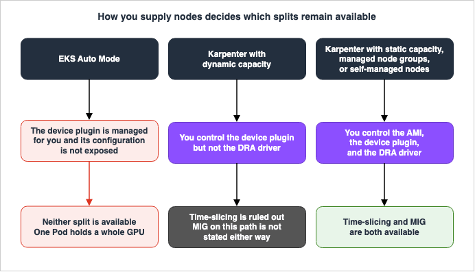
Time-slicing can only be used with Karpenter if you are using static capacity provisioning.
Time-slicing is not currently available in EKS Auto Mode.
On the same page, the "Considerations" section for device plugins provides reasons, as well.
EKS Auto Mode manages the NVIDIA device plugin and does not expose its configuration. Because
time-slicing requires device plugin configuration, you cannot apply a time-slicing configuration
on EKS Auto Mode nodes.
The MIG page also reaches the same conclusion for the same reason.
You cannot enable MIG on EKS Auto Mode nodes.The reason is clear: both methods require device plugin configuration, and EKS Auto Mode does not expose that configuration. Therefore, neither time-slicing nor MIG can be enabled on nodes using EKS Auto Mode. If you want to use either of these, you will need to use a method that allows you to manage the configuration yourself, such as static Karpenter nodes, EKS managed node groups, or self-managed nodes.
Explaining EKS Auto Mode itself is out of scope for this article. The only point made here is that if either of these two sharing methods is in the plan, Auto Mode drops out of the options. For MPS, no statement about whether it works on Auto Mode was found.
| Node Provisioning Method | Time-Slicing | MIG |
|---|---|---|
| EKS Auto Mode | Not supported. Officially stated. | Not supported. Officially stated. |
| Karpenter (Static Capacity) | Supported | Supported |
| Karpenter (Dynamic Capacity) | Not supported. Officially stated. | Not explicitly stated. |
| EKS Managed Node Groups | Supported | Supported |
| Self-Managed Nodes | Supported | Supported |
The MIG cell in the third row reads as not explicitly stated because it could not be confirmed. Regarding the DRA driver path, the MIG page explicitly requires static capacity as a prerequisite. For the device plugin path, the comparison table with the DRA driver lists Karpenter as a node provisioning method without distinguishing between static and dynamic capacity, and the MIG procedures themselves use Karpenter. Those two can be read as indicating that dynamic capacity works, but no sentence stating it outright was found. Rather than filling the cell by inference, it is left as something that could not be confirmed.
11.2 The AMI Version Carries Conditions Too
Even if the delivery method meets the requirements, the AMI itself has additional conditions. Neither option is available on older versions.| Condition | Required Version |
|---|---|
| Using MIG with Bottlerocket | Bottlerocket 1.34.0 or later |
| Disabling the built-in device plugin in Bottlerocket and using the DRA driver | Bottlerocket 1.63.0 or later |
Using MIG with g7 | NVIDIA driver 595 or later. As noted in Section 10.2, this is not currently included in the Amazon EKS optimized AMI. |
Pay close attention to the behavior when the second condition cannot be met. Older versions do not allow you to disable the built-in device plugin. As described in Section 3.4, if the device plugin and the DRA driver run on the same node, devices may be silently assigned twice. If you install the DRA driver on a version that does not allow disabling the built-in device plugin, you will encounter this situation.
11.3 The Two Paths Reverse Who Decides Which Pods Share
The key difference, and one that is often overlooked, is that the method for determining which entities can share resources varies significantly depending on the path.In the device plugin path, the device plugin advertises slots to the whole node. Any Pod requesting
nvidia.com/gpu, regardless of its namespace, can land on a slot at the scheduler's discretion. The scheduler determines which entities can share resources.This is not the case with the DRA driver path.
Pods share a GPU only by referencing the same ResourceClaim or ResourceClaimTemplate, which is
namespace-scoped, so sharing cannot cross namespaces. System-mediated sharing is a proposed
future capability.
Only Pods that point explicitly at the same
ResourceClaim share a GPU. Since a ResourceClaim belongs to a namespace, sharing does not cross the namespace. The individual who wrote the manifest determines which entities can share resources.This difference has a direct impact on multi-tenant designs. Where namespaces separate tenants, time-slicing through the DRA driver path does not cross tenant boundaries. However, with the device plugin path, the same functionality can potentially cross tenant boundaries. As Section 2 established, time-slicing provides no memory isolation. Therefore, the device plugin path creates a potential pathway for one tenant's Pod to consume the memory of another tenant's Pod.
However, this should not be interpreted as an isolation feature on the DRA side. The user guide describes this as a user-mediated sharing mechanism, rather than an isolation mechanism. Furthermore, system-mediated sharing is explicitly mentioned as a potential future proposal. In other words, the current limitation of not crossing namespaces is not a design goal, but rather a reflection of the current implementation status.
12. The Alpha Label Is on the Driver, Not on Kubernetes
12.1 Do Not Conflate the Two Stability Levels
When planning GPU sharing in Amazon EKS, stability sits on two distinct layers. Confusing these two layers could lead you to interpret a "GA" designation as indicating that alpha features are suitable for production environments.Kubernetes' Dynamic Resource Allocation is a feature that reached General Availability (GA) in Kubernetes 1.34. Section 9 of Gang Scheduling and Dynamic Resource Allocation on Amazon EKS holds the list of Kubernetes feature gates and their stability in a table. This article defers to it.
In addition, the NVIDIA DRA driver itself has its own set of feature gates. These are not Kubernetes feature gates, but values set in the driver's Helm chart. The functionality related to GPU sharing is located within this layer.
The Amazon EKS user guide briefly mentions this layer in a single sentence.
Dynamic MIG and time-slicing are in alpha state in the NVIDIA DRA driver.The same page also provides recommendations based on this understanding. When utilizing GPU sharing features such as MIG or time-slicing, it recommends either using the DRA driver's static configuration or utilizing the NVIDIA device plugin.
12.2 The Feature Gates on the Driver Side
Specifically, these are configured as follows. All are disabled by default.| Feature | Driver-Side Feature Gate | Status |
|---|---|---|
| DRA Driver Path Time-Slicing | TimeSlicingSettings | alpha, disabled by default |
| Dynamic MIG | DynamicMIG | alpha, disabled by default |
| Static MIG | None | Does not require a feature gate |
DynamicMIG also has compatibility restrictions. It cannot be used in conjunction with PassthroughSupport, NVMLDeviceHealthCheck, or MPSSupport. MPS and dynamic MIG cannot both be turned on in one driver.The user guide also describes what happens when requesting DRA driver path time-slicing without enabling the corresponding feature gate.
If you request the TimeSlicing sharing strategy without enabling this feature gate, the driver
fails to prepare the device and the Pod stays in ContainerCreating with a
FailedPrepareDynamicResources event that reports
error validating GPU config: unknown GPU sharing strategy: TimeSlicing.
The symptom is that it stops at
ContainerCreating, which is hard to tell apart from an image pull or a volume problem. The FailedPrepareDynamicResources event tells them apart.12.3 What Dynamic MIG Assumes
Dynamic MIG allows drivers to create and destroy MIG partitions based on workload demands, eliminating the need to pre-allocate partitions. While appealing, it is currently in alpha and has three conditions.- Replacing Static Discovery. The driver will discard MIG partitions that it did not create during the GPU's kubelet plugin startup. It explicitly states that this should not be enabled on nodes that already have existing partitions that need to be preserved.
- Hardware Generation Requirements. MIG mode can only be enabled on-the-fly for Hopper and later generations. It is not possible on earlier generations, such as Ampere's A100.
- Dependency on Kubernetes Features. Dynamic MIG relies on the "partitionable devices" feature, which is enabled by default in Kubernetes 1.36 and later. In earlier versions, it is disabled by default, preventing the scheduler from allocating dynamically created MIG devices.
The second condition is the most practically significant. Even if you plan to use dynamic MIG on A100 nodes, the hardware itself does not support enabling the mode on-the-fly.
13. Where the Primary Sources Disagree
Regarding GPU sharing in Amazon EKS, both the user guide and the best practices guide contain descriptions of the feature. Within the range checked, four places disagreed. Readers hit these when they go to the official pages, so it is worth setting out which page is speaking about what.The date of that check is September 8, 2026. This section will become obsolete if either of these documents is updated.
13.1 Whether DRA Works with Karpenter
The best practices guide lists the prerequisites for using DRA, and in the node group row, it states this in parentheses.Amazon EKS managed node groups (DRA is currently supported only by managed node groups with
AL2023 and Bottlerocket NVIDIA optimized AMIs, not with Karpenter)In contrast, the Amazon EKS user guide, "Manage hardware devices," details the conditions with a finer granularity.
DRA is not currently compatible with Karpenter when using dynamically provisioned capacity. You
must use static capacity provisioning in Karpenter, or EKS managed node groups or self-managed
nodes with DRA drivers.
Saying that DRA does not work with Karpenter, and saying that it does not work with dynamically provisioned Karpenter capacity, are two different statements. The user guide states outright that static capacity does work, and similar statements appear on the DRA driver page and the NVIDIA GPU page. Therefore, it is reasonable to follow the information presented across these three pages.
13.2 Whether MPS on the DRA Driver Is Alpha
Within the same page of the user guide there is a place where the reading splits. The prose explicitly mentions only two features.Dynamic MIG and time-slicing are in alpha state in the NVIDIA DRA driver.In the comparison table on the same page, the GPU sharing row lists three options on the DRA driver side: Dynamic MIG, MPS, and time-slicing, and includes a notation indicating "alpha" at the beginning of the row. The interpretation differs depending on whether MPS is included.
There is one piece of evidence to consider. The driver installation instructions mention a feature gate named
MPSSupport, and list it as incompatible with DynamicMIG. The existence of this feature gate suggests that it is not enabled by default. However, the stability of that gate itself was not stated anywhere in the pages reviewed.This article does not offer a definitive conclusion. If MPS on the DRA driver path is in the plan, it is best to directly consult the NVIDIA DRA driver release notes. The user guide itself also advises users to check the driver release notes for the most up-to-date information.
13.3 Whether the G Family Supports MIG
The best practices guide contains a table that maps instance families and features supported by DRA. Within that table, the rows for G5, G6, and G6e all indicate "No" in the column for MIG compatibility. Notably, the table does not include rows forg7 and g7e.The MIG page of the user guide lists both
g7.48xlarge and g7e.48xlarge as instance types that support MIG, and includes their respective profiles.The absence of an instance from the table should not be taken as definitive proof that it is not supported. It is reasonable to assume that these two instance types are from a later generation than the G5, G6, and G6e instances listed in the table, and that the cross-service compatibility table has not caught up. Do not build a general rule out of this table that the G family cannot do MIG.
It is not uncommon for cross-functional compatibility tables to lag the product documentation of the same organization. When using the completeness of a table to argue against a feature, it is important to consider when that table was last updated.
13.4 Whether MIG Isolates Two Things or Three
As seen in Section 5.1, two different pages refer to different items that MIG isolates.| Page | Items Referenced |
|---|---|
| MIG page | Memory, fault |
| Time-slicing page | Memory, compute |
Neither is incorrect. The MIG page lists compute units separately among the things that become dedicated, so leaving compute out of the list of isolated items does not fundamentally change its meaning. The time-slicing page describes what cannot be obtained through time division, so it is not necessary to mention faults.
The issue arises for readers who only read one of the pages. If a reader only reads the MIG page, it looks as though compute is not isolated. Conversely, if a reader only reads the time-slicing page, it might seem that faults are not isolated. Either interpretation could influence design decisions.
This pattern has the same shape as the failures this article has been tracking. It is important to remember that a description being correct does not guarantee that readers will understand it correctly.
14. Failure Modes and Anti-Patterns
14.1 Assuming That Splitting Means Being Protected
This is the most common failure type. You raise time-slicing to four slots, and four Pods land on the same GPU. From Kubernetes' perspective, each of the four Pods appears to have its own GPU. Consequently, it might be incorrectly assumed that they do not interfere with each other.The user guide refutes this assumption head-on. Pods that share a GPU share its memory, and one Pod could potentially consume memory that another Pod requires. This configuration should not be considered a basis for multi-tenant isolation.
The symptom is when a Pod from one tenant experiences an out-of-memory error, while nothing looks wrong in that tenant's own memory usage. As discussed in Section 3, it is impossible to identify the root cause tenant using GPU metrics alone.
The fix is to migrate to MIG if memory isolation is a requirement. If the current instance type does not support MIG, the node will not be able to meet that requirement. This necessitates re-evaluating the selection of instance types.
14.2 Building Production on an Alpha Feature
Dynamic MIG appears easier to operate, as it does not require pre-partitioning. The time-slicing functionality for the DRA driver also seems logical, as configurations can be declared usingResourceClaim. However, both features are currently in the alpha stage and are disabled by default.The symptom of an issue is when Pods get stuck in the
ContainerCreating state after deploying configurations without enabling the feature gate. Because the symptoms are similar to issues with image retrieval or volume problems, troubleshooting can be time-consuming.The fix is to follow the official guidelines. When using the GPU sharing feature, it is recommended to either use a static configuration for the DRA driver or utilize the NVIDIA device plugin.
14.3 Choosing a Design That Does Not Work on EKS Auto Mode
This scenario occurs when you decide on a configuration during the design phase, and later discover that your cluster is running in EKS Auto Mode during implementation. Neither time-slicing nor MIG will work on nodes within an EKS Auto Mode cluster. This is because Auto Mode manages the device plugins and does not expose their configuration settings.The symptom is the inability to find a location to apply your settings. Instead of encountering errors, you simply will not find an entry point to configure them.
The fix is to adjust how the nodes are provisioned. You can configure your environment to provision nodes that share GPUs using either a static Karpenter configuration or a managed node group, while leaving the rest of your cluster in Auto Mode. There is no need to take the entire cluster out of Auto Mode.
14.4 Running Distributed Training on a MIG-Enabled Node
To utilize P-family nodes dedicated to training for inference during periods when training is idle, enable MIG. However, this will prevent distributed training from running on those nodes. MIG does not support NCCL, and GPU-to-GPU P2P communication is also unavailable.The symptom is that the collective communication fails to initialize. The node itself is healthy, the GPUs are visible, and workloads running on a single GPU function correctly.
The fix is to separate nodes that have MIG enabled from those that do not. There is no configuration that allows both MIG and distributed training to run on the same GPUs. Furthermore, plan for GPU resets, which may require restarting the node, when switching between MIG modes.
14.5 Dividing Performance Out of a Profile Name
This is the type that divides performance out of the profile name. For example, it assumes that if1g.10gb represents one-seventh of 7g.80gb, then 1g.10gb must have one-seventh of the performance. However, the documentation explicitly refutes this assumption, citing that memory bandwidth and cache behavior vary between profiles.The symptom is a total throughput that falls short of expectations after partitioning.
The fix is, as stated in the documentation, to measure your workload using the profile you intend to use before determining the partition size. The profile name indicates capacity, not performance.
14.6 Requesting Two Time-Slicing Slots
There is a misunderstanding that requesting two slots for a single Pod will result in double the processing power. This is not the case. The user guide calls this a common misconfiguration and recommends turning on the setting that rejects such requests.The symptom is the hardest to see of any type in this section. The Pod starts, runs, and raises no error. However, it will operate using only half the resources it was intended to utilize, based on the assumption of having two slots.
The fix is to enable that setting. Rather than detecting the mistake, it stops the mistaken request from being accepted. As described in Section 2.3, the name of this key differs between Bottlerocket and AL2023.
14.7 Leaving the DRA Driver and the Device Plugin on the Same Node
This is the type where you leave an existing device plugin in place while trying out the DRA driver. Or the type where you install the DRA driver on Bottlerocket without disabling the built-in one. Both configurations will yield the same result.As described in Section 3.4, the user guide refers to this as a silent device over-allocation. Two different mechanisms independently advertise the same physical device, and neither is aware of the other.
The symptom here is the hardest to catch in this section. Pods will start, the node will report as Ready, and
nvidia-smi will respond normally. Without performing the UUID verification described in Section 9.4, it is hard to notice that Pods that should each hold a device exclusively are sharing one.The fix is to avoid this configuration. The user guide advises uninstalling the existing device plugin before installing the corresponding DRA driver, or deploying them on separate nodes. On Bottlerocket, ensure you are using a version that allows you to disable the built-in device plugin.
14.8 Assuming That Enabling MIG Raises Density by Itself
This issue occurs when MIG is enabled in Bottlerocket without specifying a profile. As mentioned in Section 5.4, the GPU will use the largest available profile. Since it allocates all seven compute slices to a single instance, there is only one instance per GPU.The symptom is that the number of
nvidia.com/gpu resources the node advertises does not change from the physical number of GPUs. MIG mode is enabled, and nvidia-smi reports this as well, but the GPUs are not partitioned.The fix is to explicitly define the profile you want to use. Enabling MIG and partitioning into a specific granularity are separate operations.
15. Frequently Asked Questions
Q. Does enabling time-slicing increase GPU utilization?A. Yes, but this is limited to specific workloads. What the user guide lists as the case where it rises is a workload whose GPU utilization is consistently low. Examples include inference services that spend significant time idle between requests, or development environments shared by multiple developers. Conversely, it's stated that time-slicing can reduce efficiency in training workloads, due to increased context switching. This article does not discuss specific performance improvement figures.
Q. If I enable MIG, can I safely run workloads in a multi-tenant environment?
A. Not solely based on that. Within a single GPU, MIG isolates memory, compute, and fault domains. However, these three are written across two pages, so reading only one of them shows just two. Furthermore, this is distinct from node and kernel isolation. Workload Isolation Levels on Amazon EKS covers what may share the same node. Splitting the GPU says nothing about the layer that article covers.
Q. Can I combine time-slicing and MIG?
A. You cannot effectively combine them. Both can exist on the same node, and as noted in Section 9.3 a node can carry partitioned and unpartitioned GPUs side by side. What you cannot do is layer them on the same device. The user guide states explicitly that time-slicing has no effect on a MIG instance. While the configuration will be accepted, the hardware behavior will not change. The user guide directs you to MPS if you want to split a single MIG instance across several containers.
Q. Can I determine my configuration by looking at a Pod with the line
nvidia.com/gpu: 1?A. No. That single line is not enough to determine your configuration. It could represent a shared configuration, time-slicing, or MIG's single strategy – all resulting in the same string. To determine your configuration, you need to examine the node. Verify whether the node advertises a number of
nvidia.com/gpu resources that matches the physical number of GPUs, whether resources starting with nvidia.com/mig- are advertised, or whether nvidia-smi reports MIG mode as enabled.Q. I'm using EKS Auto Mode, but I want to share GPUs.
A. You cannot enable either time-slicing or MIG on nodes managed by EKS Auto Mode. This is because Auto Mode manages the NVIDIA device plugin and does not expose these configuration options. You can achieve GPU sharing by configuring only the nodes you want to share using static Karpenter or managed node groups.
Q. I'm using
g6e. Memory isolation is now a requirement.A. The
g5, g6, and g6e families are not compatible with MIG. Therefore, these instance types do not provide the memory isolation the user guide describes. To meet your requirements, you will need to migrate to MIG-compatible instance types, specifically the P family or the Blackwell-based g7 and g7e. Regarding g7, it's also important to verify that the driver version included in the Amazon EKS-optimized AMI at the time of verification is compatible with the MIG requirements.Q. Can dynamic MIG be used to switch partitions while they are in operation?
A. This is not currently possible with the standard path. Dynamic MIG is in alpha and is disabled by default. Furthermore, only generations Hopper and later can enable MIG mode on the fly; this is not possible with Ampere-based A100 instances. Also, prior to Kubernetes 1.36, the scheduler cannot allocate dynamically created MIG devices. For GPU sharing features the user guide recommends either the DRA driver's static configuration or the device plugin.
Q. I want to know which of the shared Pods is consuming the GPU memory.
A. While time-slicing is enabled, container-level attribution is not possible. The user guide states plainly that NVIDIA Data Center GPU Manager cannot do this. While GPU-level metrics remain, allowing you to determine that memory is being utilized, it is not possible to identify which Pod is consuming it. If attribution is a requirement, you will need to consider an alternative isolation method.
Q. I changed the number of shared slots, but it's not reflected.
A. The NVIDIA device plugin does not monitor changes to the
ConfigMap for time-slicing. After updating the configuration, you will need to restart the device plugin Pod. The user guide carries this as a note.Q. Can you estimate the performance of a MIG instance based on its profile name?
A. No, you cannot. The user guide states that an instance holding one of seven compute slices does not necessarily provide a proportional allocation of the GPU, citing differences in memory bandwidth and cache behavior across different profiles. The user guide tells you to benchmark your workload on the profile you intend to use before you size the partitions.
Q. Does this article specify which path to use to request devices?
A. It does not. Section 8 of Gang Scheduling and Dynamic Resource Allocation on Amazon EKS addresses the choice of allocation path itself. This article covers the constraints that attach to the splitting side once the path is settled. From the perspective of splitting, two factors are particularly relevant to path selection: firstly, the time-slicing and dynamic MIG on the DRA driver path are both alpha, and secondly, the fact that the sharing of the DRA driver path does not cross namespaces.
16. Summary
There are three methods for dividing a single GPU across multiple Pods, and each method offers a different level of protection from neighboring Pods.- Time-slicing divides resources sequentially. The user guide states outright that it isolates neither memory nor compute. It operates solely through software and is compatible with all NVIDIA GPU instance types on AWS.
- MPS allows multiple CUDA processes to run concurrently. The documentation calls its isolation stronger than time-slicing, but no dedicated page lists what it leaves unisolated. It cannot be used on the same physical GPU as time-slicing.
- MIG divides the GPU using hardware. It provides dedicated memory, compute units, and memory bandwidth, and the isolation obtained covers memory, compute, and fault. However, there is no single official document that mentions all three features together; the information is spread across two separate pages. As a trade-off, it disables NCCL and GPU-to-GPU P2P communication, and requires GPU resets to modify configurations.
The three are not peer options at the same level. Time-slicing does not work with MIG instances, and only MPS can be used to partition MIG instances.
Whether these options are available depends on how the nodes are provisioned. In EKS Auto Mode, neither time-slicing nor MIG can be enabled. This is because Auto Mode manages the device plugin and does not expose configuration options. For Karpenter, the documentation states that time-slicing is limited to static capacity. Whether MIG works with dynamically provisioned Karpenter capacity could not be confirmed.
Stability is presented in two layers. Kubernetes' Dynamic Resource Allocation reached General Availability (GA) in version 1.34, but NVIDIA's DRA driver's dynamic MIG and time-slicing features are still in alpha and are disabled by default. For GPU sharing features the user guide recommends either the DRA driver's static configuration or the device plugin.
Returning to the initial question: The line
nvidia.com/gpu: 1 in a Pod's specification only indicates the number of GPUs being requested and does not specify any protection against neighboring Pods potentially accessing its memory. This single line can have four different meanings, and the node-side configuration determines which meaning applies. Splitting and being protected get settled in two different places.The same gap sits on either side of this one. In the model API, three settings are all called a limit, and only one of them is a ceiling the runtime enforces: Controlling How Much a Model Thinks. In an organization, listing a product in a catalog narrows what a developer can pick without narrowing what that developer is permitted to do: Internal Developer Platforms on AWS.
17. References
- Manage hardware devices on Amazon EKS
- Manage NVIDIA GPUs on Amazon EKS
- Use the NVIDIA DRA driver or device plugin on Amazon EKS
- Use multi-instance GPUs (MIG) with NVIDIA GPUs on Amazon EKS
- Use time-slicing with NVIDIA GPUs on Amazon EKS
- Amazon EKS Best Practices Guide - Compute and Autoscaling
- Review release notes for Kubernetes versions on standard support
References:
Tech Blog with curated related content
Written by Hidekazu Konishi