Amazon EKS Networking Deep Dive - VPC CNI, IP Address Management, Security Groups for Pods, and Pod Connectivity
First Published:
Last Updated:
FailedCreatePodSandBox, and the underlying Amazon EC2 API returns InsufficientFreeAddressesInSubnet. The reason is that EKS gives every Pod a real VPC IP address through the Amazon VPC Container Network Interface (VPC CNI) plugin, so your Kubernetes data plane consumes the same address space as everything else in the VPC.This article is a Level 300+ deep dive into how that mechanism actually works and how to operate it at scale. It covers the internals of the VPC CNI (
aws-node, the CNI binary, and the ipamd daemon), how the warm pool of IPs and prefixes is managed, how max-pods is derived from the instance type, and the three ways to escape IPv4 exhaustion — prefix delegation, custom networking, and IPv6. It then covers per-Pod micro-segmentation with security groups for Pods and Kubernetes network policies, what changes under EKS Auto Mode, how to diagnose IP and connectivity failures, and finally a single end-to-end architecture that combines the IP-conservation and security building blocks into one scalable, secure Pod network.The scope is deliberately the network internals, not an EKS getting-started guide. For the history of the service, see my AWS History and Timeline of Amazon EKS; for VPC fundamentals and vocabulary, see AWS History and Timeline of Amazon VPC and the AWS Networking Glossary. VPC-level connectivity selection (peering, Transit Gateway, PrivateLink) is covered in my AWS VPC Connectivity Decision Guide, and generic reachability triage in the AWS VPC Network Troubleshooting Guide. All service behavior below was verified against the Amazon EKS User Guide and the Amazon EKS Best Practices Guide; this article contains no pricing figures — for cost, follow the official pricing links in the References.
1. Introduction: Why Pod IP Addressing Is an EKS Design Decision
Most CNI plugins on other platforms run an overlay network: Pods get addresses from a private, cluster-internal range that is invisible to the surrounding network, and traffic is encapsulated. The Amazon VPC CNI takes the opposite approach. Each Pod receives an IP address from the VPC itself, drawn from the subnet attached to the node. The benefit is that a Pod is a first-class citizen of the VPC: it can be reached directly, security groups and route tables apply to it natively, VPC Flow Logs see it, and there is no encapsulation overhead. The cost is that Pods consume VPC IP space at the same density they are scheduled, which makes subnet sizing and IP management a real architectural decision rather than an afterthought.This is also why EKS networking rewards understanding over defaults. Because Pods sit directly on the VPC, the same tools you already use for EC2 — security groups, route tables, VPC Flow Logs, Reachability Analyzer — apply unchanged, and there is no overlay to debug when a connection fails. The flip side is that a mistake in subnet sizing or security-group scope surfaces as a hard scheduling or connectivity failure rather than a slow degradation, so the mechanisms in this article are operational knowledge, not trivia.
That trade-off is the throughline of this article. Every feature that follows — warm-pool tuning, prefix delegation, custom networking, IPv6 — exists to reconcile high Pod density with a finite VPC address space, while security groups for Pods and network policies layer segmentation on top of that flat, routable model. To use any of them well, you first need to understand the moving parts inside
aws-node.2. How the Amazon VPC CNI Works
2.1 The Two Components: CNI Binary and ipamd
The VPC CNI is deployed as a Kubernetes DaemonSet namedaws-node in the kube-system namespace, so one instance runs on every worker node. It has two distinct components:- The CNI binary runs on the node's root filesystem and is invoked by the kubelet whenever a Pod is added to or removed from the node. Its job is to wire up the host and Pod network namespaces — creating the virtual interface, configuring routes, and plumbing the Pod's IP — so that Pod-to-Pod communication works. All containers in a Pod share one network namespace and reach each other over localhost.
- ipamd (the IP Address Management daemon) is a long-running, node-local process inside
aws-node. It is responsible for managing the Elastic Network Interfaces (ENIs) attached to the node and for maintaining a warm pool of IP addresses (or prefixes) so that new Pods can be assigned an IP instantly without waiting on an EC2 API call.
This separation matters operationally: the CNI binary is on the hot path of every Pod create/delete (latency-sensitive, synchronous), while
ipamd runs asynchronously, calling EC2 APIs to attach ENIs and allocate addresses ahead of demand.2.2 ENIs, Slots, and the Warm Pool
When EC2 launches an instance, it creates and attaches a primary ENI in the node's primary subnet. As the VPC CNI initializes, it allocates a pool of slots from the node's subnet onto that ENI. Depending on configuration, a slot is either a single secondary IP address (the default, "secondary IP mode") or a/28 prefix (prefix delegation mode, covered in Section 4).Each ENI supports a fixed number of slots that depends on the instance type, and each instance type supports a maximum number of ENIs. As Pods are scheduled and the pool of free slots runs low,
ipamd attaches additional secondary ENIs, each with its own pool of slots, until the instance reaches its ENI limit. ipamd also pre-attaches "warm" ENIs and pre-allocates warm slots so that Pod startup is fast. The number of ENIs an instance can attach and the number of IPs per ENI is therefore one of the two hard ceilings on Pod density (the other being compute resources).A concrete example makes the warm pool tangible. Take a cluster of three
c5.large nodes (3 ENIs, up to 10 IPs per ENI) with default settings. Two of the nodes run a CoreDNS Pod and one is empty. On each node running CoreDNS, the CNI keeps two ENIs attached: 2 ENIs x 10 IPs = 20, minus 2 primary IPs (one per ENI) and minus 1 IP for the CoreDNS Pod leaves 17 warm IPs ready for instant scheduling. The empty node keeps a single ENI: 10 IPs minus 1 primary = 9 warm IPs. Across the cluster that is 17 + 17 + 9 = 43 warm IPs held in reserve so the next Pods launch without an EC2 round trip. Those 43 addresses are consumed from the VPC even though no workload is using them — which is exactly why warm-pool tuning matters on constrained subnets.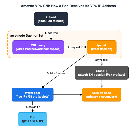
2.3 The Pod IP Assignment Flow
When the kubelet receives a request to add a Pod, the sequence is:- The kubelet invokes the CNI binary.
- The CNI binary asks ipamd for an available IP address from the warm pool.
ipamdreturns a free IP that is already attached to one of the node's ENIs.- The CNI binary wires the Pod's network namespace to that IP and configures host routes.
Because the IP came from the warm pool, no synchronous EC2 API call is on this path. In the background,
ipamd notices the pool has shrunk and asynchronously requests more secondary IPs (or attaches another ENI) to top the pool back up.When a Pod is deleted, the VPC CNI does not immediately return the IP. It places the address in a 30-second cool-down cache. IPs in cool-down are not handed to new Pods; the delay gives
kube-proxy on every node time to finish updating its iptables rules so traffic is not sent to a recycled IP that now belongs to a different Pod. After the cool-down expires, the IP returns to the warm pool. If the number of warm IPs or ENIs then exceeds the configured targets, ipamd releases the surplus back to the VPC.By default, Pods inherit the security groups of the node's primary ENI — every Pod on a node shares the node's security groups. Section 7 shows how to override that per Pod.
2.4 How max-pods Is Determined
Because each Pod consumes one IP slot, the maximum number of Pods per node in secondary IP mode follows directly from the instance's ENI and IP limits:max-pods = (number of ENIs * (IPv4 addresses per ENI - 1)) + 2- 1 per ENI accounts for the primary IP of each ENI (not assignable to a Pod), and the + 2 accounts for the host-networking Pods that EKS requires on every node — kube-proxy and aws-node (VPC CNI) — which do not consume a secondary IP. For example, an m5.large supports 3 ENIs with 10 IPv4 addresses each, giving (3 * (10 - 1)) + 2 = 29 Pods.That ENI-derived value is not always the value applied to a node. EKS resolves
max-pods by a precedence order (highest to lowest):- Managed node group enforcement — for a managed node group without a custom AMI, EKS caps
max-podsin the node's user data:110for instances with fewer than 30 vCPUs and250for instances with more than 30 vCPUs. This cap takes precedence over everything else. - kubelet maxPods — an explicit value set in the kubelet config (for example via a launch template with a custom AMI).
- nodeadm maxPodsExpression — evaluated by
nodeadminNodeConfigwhen not set by a higher-precedence source. - Default ENI-based calculation — the AMI's own calculation from ENIs and IPs when nothing else is set.
The caps of 110/250 exist because Kubernetes itself does not recommend packing arbitrarily many Pods onto a node, and because on smaller instances you would exhaust CPU and memory long before IPs. Authoritative per-instance values live in eni-max-pods.txt and the resource limits file in the VPC CNI repository — always derive from those rather than memorizing numbers, because newer instance generations change ENI and IP counts.
Remember to budget for infrastructure DaemonSets — CoreDNS, the AWS Load Balancer Controller, metrics-server, log and metric agents — which all count toward
max-pods. A node that the math says holds 110 Pods may realistically hold far fewer workload Pods once system Pods are subtracted.3. IP Address Management and Warm Pools
The behavior ofipamd is governed by a small set of environment variables on the aws-node DaemonSet. Tuning them is the difference between fast Pod launches and conserving scarce VPC addresses.3.1 The Warm-Pool Environment Variables
- WARM_ENI_TARGET (integer) — the number of whole warm ENIs to keep attached. An ENI is "warm" when it is attached but none of its IPs are in use by a Pod. The default is
1: as soon as any IP from an ENI is used,ipamdattaches another ENI so a full ENI's worth of IPs is always ready. This favors burst-friendly fast scheduling but holds the most addresses. - WARM_IP_TARGET (integer) — the number of warm IP addresses to keep available on already-attached ENIs (IPs that could be assigned without attaching a new ENI). This is a finer-grained, more frugal knob than
WARM_ENI_TARGET. - MINIMUM_IP_TARGET (integer) — the floor on total allocated IPs at any time, commonly used to front-load IP allocation at instance launch so a known baseline of Pods schedules instantly.
- WARM_PREFIX_TARGET (integer, prefix mode only) — the number of
/28prefixes to keep allocated beyond current need.
A node is considered to have enough capacity when either
WARM_ENI_TARGET or the pair WARM_IP_TARGET + MINIMUM_IP_TARGET is satisfied. When WARM_IP_TARGET and/or MINIMUM_IP_TARGET are set, they override WARM_ENI_TARGET (and WARM_PREFIX_TARGET in prefix mode).3.2 Behavior and Trade-offs by Example
Consider an instance whose ENIs support 20 IPs each, withWARM_IP_TARGET=5 and WARM_ENI_TARGET=0. Only one ENI stays attached until the 16th IP is needed; at that point ipamd attaches a second ENI and consumes another 20 addresses from the subnet CIDR. With MINIMUM_IP_TARGET=100 on a freshly launched instance whose ENIs hold 10 IPs each, ipamd immediately attaches enough ENIs to reach 100 addresses — regardless of WARM_IP_TARGET or WARM_ENI_TARGET — so the node can absorb a large initial scheduling burst.The critical operational point: warm ENIs and warm IPs still consume real VPC addresses even though no Pod is using them. The default
WARM_ENI_TARGET=1 is generous; on IP-constrained subnets, switching to a small WARM_IP_TARGET (and a sensible MINIMUM_IP_TARGET) can reclaim a large amount of address space at the cost of slightly slower scale-up. A reasonable starting point on tight subnets is MINIMUM_IP_TARGET set to your typical steady-state Pod count per node and WARM_IP_TARGET to your expected burst size.To see
WARM_ENI_TARGET in motion, picture an instance with 2 ENIs that each support 5 IPs and WARM_ENI_TARGET=1. If exactly 5 IPs are in use, the CNI keeps both ENIs attached: the first ENI is fully consumed and the second is entirely warm. The moment a 6th Pod needs an IP it is served from the second ENI, which is no longer warm — so the CNI immediately attaches a third ENI to restore one warm ENI. This is why WARM_ENI_TARGET can hold far more spare addresses than you expect on instances with many IPs per ENI, and why WARM_IP_TARGET is the better lever when addresses are scarce.3.3 Configuring the Variables
You set these on the DaemonSet directly:# Conserve IPs: keep a small headroom instead of a whole warm ENI
kubectl set env daemonset aws-node -n kube-system WARM_ENI_TARGET=0
kubectl set env daemonset aws-node -n kube-system WARM_IP_TARGET=5
kubectl set env daemonset aws-node -n kube-system MINIMUM_IP_TARGET=10kubectl describe daemonset aws-node -n kube-system | grep -A1 -E "WARM_|MINIMUM_IP"WARM_ENI_TARGET, WARM_IP_TARGET, MINIMUM_IP_TARGET, and the CNI modes — are not managed fields and are preserved. Still, set them through the add-on's configuration values (rather than ad-hoc kubectl set env) so your intent survives add-on updates and is captured in your infrastructure code.4. Solving IP Exhaustion: Prefix Delegation
4.1 The Mechanism
In the default secondary IP mode, each slot on an ENI holds exactly one IP, so density is limited byENIs * IPs-per-ENI. Prefix delegation changes what a slot holds: instead of a single address, a slot holds a /28 IPv4 prefix — a contiguous block of 16 addresses. The instance's maximum number of ENIs and the maximum number of slots per ENI stay the same, but each slot now yields 16 usable Pod IPs instead of one.Prefix delegation is available in VPC CNI version
1.9.0 and later, and is enabled by setting ENABLE_PREFIX_DELEGATION=true. It requires AWS Nitro-based instances, because only Nitro instances support attaching prefixes to ENIs. (On IPv6 clusters, prefix mode is the default and the only mode — see Section 6.)The slot accounting is precise: the number of IP addresses an ENI can carry depends on the instance type, and each prefix counts as one of those addresses. For example, a
c5.large ENI has a limit of 10 IPv4 addresses. Subtracting the primary address, you can assign up to 9 prefixes to that ENI — and 9 prefixes deliver 9 * 16 = 144 Pod IPs on a single ENI, versus 9 secondary IPs in the default mode. For every additional individual secondary IP you keep on an ENI, you can assign one fewer prefix.The gain is most dramatic where ENI counts are low. A Windows node, for example, supports only a single ENI, so prefix mode is the difference between roughly a dozen Pod IPs and well over a hundred on the same instance. On Linux nodes with several ENIs the absolute numbers are higher, but the principle is identical: you trade a small, bounded amount of potential address waste (at most one unused
/28, i.e. up to 15 spare IPs per node) for a large jump in density and faster Pod launches.4.2 Warm Pool in Prefix Mode
During node bootstrap, the CNI assigns one or more prefixes to the primary ENI and keeps a warm pool of prefixes. The warm pool is governed byWARM_PREFIX_TARGET (default 1), with WARM_IP_TARGET and MINIMUM_IP_TARGET overriding it when set. As Pods are scheduled, the CNI first tries to allocate a new prefix to an existing ENI; only if that ENI is at its slot limit does it attach a new ENI.This ordering is a deliberate performance optimization: allocating a prefix to an existing ENI typically completes in under a second, while attaching a new ENI can take up to 10 seconds. In prefix mode, most worker nodes need only a single ENI, which both speeds up scaling and reduces the number of EC2 API calls — a major factor in large, spiky clusters where API throttling delays Pod scheduling.
To conserve IPv4 addresses, the recommended
WARM_PREFIX_TARGET=1 is usually a good balance. If you need to be more frugal, set WARM_IP_TARGET to a value below 16 so the CNI does not keep an entire spare prefix attached.There is a second-order benefit beyond density. In a large IPv4 cluster running in secondary IP mode,
ipamd must make frequent EC2 API calls to assign individual addresses during scale-up, and those calls are subject to account-level throttling — which shows up as delayed Pod scheduling during spikes. Because one /28 prefix carries 16 addresses, prefix mode sharply reduces the number of EC2 calls needed to back the same Pod count, smoothing scaling for large and bursty workloads. For most workloads a single ENI per node in prefix mode is enough.4.3 Recalculating max-pods
Because the defaultmax-pods value is computed for secondary IP mode, you must raise it to take advantage of prefixes. Enable the feature and recompute:kubectl set env daemonset aws-node -n kube-system ENABLE_PREFIX_DELEGATION=true
kubectl set env daemonset aws-node -n kube-system WARM_PREFIX_TARGET=1max-pods for prefix mode:./max-pods-calculator.sh \
--instance-type m5.large \
--cni-version 1.9.0 \
--cni-prefix-delegation-enabled--max-pods) with --use-max-pods=false, or set it on the managed node group or launch template. Keep the compute reality in mind: prefix mode can push an m5.large to hundreds of theoretical Pod IPs, but you would exhaust its CPU and memory long before then. AWS guidance is to cap max-pods at around 110 for small instances and up to 250 for large ones, not the raw IP ceiling.4.4 The Fragmentation Pitfall and Subnet CIDR Reservations
A/28 prefix must be a contiguous block of 16 addresses in the subnet. On a heavily used subnet with scattered secondary IPs, EC2 may be unable to find a contiguous block, and prefix allocation fails with:failed to allocate a private IP/Prefix address: InsufficientCidrBlocks:
There are not enough free cidr blocks in the specified subnet to satisfy the request.Two migration cautions: once prefixes are assigned, do not downgrade the VPC CNI below
1.9.0 without first deleting and recreating all nodes; and when transitioning an existing cluster, create new node groups rather than rolling existing nodes in place, because a node carrying both individual IPs and prefixes advertises inconsistent capacity. Cordon and drain the old nodes (with Pod Disruption Budgets for critical workloads), confirm Pods come up on new prefix-mode nodes, then delete the old node groups.5. Solving IP Exhaustion: Custom Networking
5.1 The Mechanism
Prefix delegation increases density per node but still draws from the primary subnet. If the primary subnet's CIDR is simply too small — a common situation when an EKS cluster is dropped into a pre-existing, address-constrained VPC — you need Pods to get addresses from a different range entirely. That is custom networking.With custom networking, Pod IPs come from a secondary VPC CIDR rather than the node's primary subnet. You define the alternate subnet (and the security groups for the secondary ENIs) in an
ENIConfig custom resource, and the VPC CNI creates secondary ENIs in that subnet. The node's primary ENI keeps using the primary VPC CIDR; Pods use the secondary CIDR.The recommended secondary range is the 100.64.0.0/10 shared address space (RFC 6598). It is non-routable CG-NAT space that corporate networks rarely use, so it is far less likely to overlap with on-premises or peered ranges than another RFC 1918 block. For example, you might attach
100.64.0.0/16 as a secondary CIDR to a VPC whose primary is 10.0.0.0/16, and run Pods on the 100.64 space while load balancers, NAT gateways, and the nodes themselves stay on the routable 10.0 space.5.2 Configuration
Enable custom networking and tell the CNI how to pick the rightENIConfig per node:kubectl set env daemonset aws-node -n kube-system AWS_VPC_K8S_CNI_CUSTOM_NETWORK_CFG=true
kubectl set env daemonset aws-node -n kube-system ENI_CONFIG_LABEL_DEF=topology.kubernetes.io/zoneENIConfig per Availability Zone, named to match the zone (so the topology.kubernetes.io/zone label on each node selects the matching config automatically):apiVersion: crd.k8s.amazonaws.com/v1alpha1
kind: ENIConfig
metadata:
name: us-west-2a
spec:
securityGroups:
- sg-0dff111a1d11c1c11
subnet: subnet-011b111c1f11fdf11ENI_CONFIG_LABEL_DEF to a custom label (for example k8s.amazonaws.com/eniConfig) and label nodes explicitly. As with prefix mode, enabling custom networking is disruptive and applies only to new nodes: existing nodes and Pods are unaffected, so the rollout pattern is to create the ENIConfig resources, launch new nodes, then cordon and drain the old ones.5.3 Constraints You Must Design Around
- The primary ENI is no longer used for Pods. Host-networking Pods still use the primary ENI's IP, and the primary ENI handles source NAT and routes Pod traffic out of the node. But because Pods only land on secondary ENIs, the per-node Pod ceiling drops. For an
m5.large, the default secondary IP mode gives(3 * (10 - 1)) + 2 = 29Pods, but with custom networking the primary ENI is no longer used for Pods, dropping the ceiling to((3 - 1) * (10 - 1)) + 2 = 20. To recover density, combine custom networking with prefix delegation: each secondary IP slot becomes a/28, raising the example to((3 - 1) * ((10 - 1) * 16)) + 2 = 290. As always, capmax-podsat a compute-sensible value (often 110), not the raw IP ceiling. - It does not solve overlapping CIDRs by itself. Custom networking gives you more address space; it does not let two VPCs with overlapping ranges talk. For overlapping-CIDR problems, a private NAT gateway (often paired with RFC 6598 space and Transit Gateway) is the documented pattern.
- If you are ready for IPv6, prefer it. Custom networking adds operational overhead (extra subnets,
ENIConfiglifecycle). If you can adopt IPv6, it removes IP exhaustion outright (Section 6), and AWS recommends re-evaluating any custom-networking setup that exists purely for IPv4 exhaustion.
100.64.0.0/10 subnets, keep only load balancers and NAT gateways on routable RFC 1918 space, and connect to on-premises or other VPCs through a Transit Gateway and a shared-services VPC. Because the Pod IP space is non-routable CG-NAT, multiple EKS clusters can reuse it without colliding, and the scarce routable addresses are spent only where they are actually needed. Where two networks have genuinely overlapping routable CIDRs, custom networking alone cannot help — a private NAT gateway is the documented way to bridge them.6. IPv6 Clusters
6.1 What IPv6 Mode Changes
EKS IPv6 mode is the most complete answer to IPv4 exhaustion: Pods and Services receive IPv6 addresses, and the limiting factor becomes compute, not addresses. Key properties to design around:- It is set at cluster creation and is irreversible. You create the cluster with
--ip-family ipv6; IPv6 is then enabled for the cluster's entire lifetime. EKS does not support dual-stack Pods (this is distinct from upstream Kubernetes dual-stack). - It is prefix-mode only, on Nitro only. IPv6 relies on prefix assignment, which is Nitro-only, so the data plane must use Nitro-based instances.
- The addressing is hierarchical. A VPC gets a fixed
/56IPv6 prefix; each subnet gets a/64; each worker node gets a/80prefix — roughly 10^14 addresses per node, which effectively removes IP scarcity. - IPv6 prefix assignment happens only at node bootstrap. This avoids the high-churn IPv4 problem where
ipamdmust make throttled EC2 calls to keep allocating addresses, and it makes theWARM_*andMINIMUM_IP_TARGETknobs unnecessary.
6.2 The Egress-Only IPv4 Model
An IPv6 Pod still has to reach IPv4-only endpoints (many AWS APIs, the internet, on-premises). EKS handles this with a secondary, host-local CNI plugin that assigns each Pod a node-local, non-routable IPv4 address from 169.254.172.0/22 (up to 1,024 addresses per node). This address is unique to the node and never advertised beyond it.When a Pod connects to an IPv4 endpoint, it does a DNS lookup, gets an A record, and the Pod's node-local IPv4 is source-NAT'd to the node's primary ENI private IPv4. For internet destinations, that VPC private IPv4 is then SNAT'd again at the IPv4 NAT gateway to a public address. Pod-to-Pod traffic across nodes always uses IPv6; the CNI configures iptables to handle IPv6 and block IPv4 between Pods. Kubernetes Services receive IPv6 ClusterIPs from an automatically assigned, immutable ULA (Unique Local Address) range.
One important caveat: this egress-only flow requires DNS64 to be disabled on the subnets where IPv6 Pods run. If DNS64 is enabled, the resolver synthesizes an IPv6 address for IPv4-only endpoints, which routes traffic through the NAT gateway's NAT64 function instead of staying in the VPC — leading to unexpected NAT gateway usage. (For the pricing implications of NAT gateway data processing, see the official VPC pricing page; this article does not quote figures.)
The control plane reaches an IPv6 data plane over cross-account ENIs (X-ENIs) that EKS provisions in dual-stack mode:
kubelet and kube-proxy run in host-network mode and bind to both the IPv4 and IPv6 addresses of the node's primary interface, while Pod-to-API-server traffic uses IPv6. This is why an IPv6 node still consumes exactly one IPv4 address from the dual-stack subnet — for the node itself — even though its Pods are IPv6-native.6.3 Migration and Load Balancing Notes
IPv6 clusters are exposed to IPv4 clients via dual-stack load balancers, which translate IPv4 to IPv6 at the edge. The upstream in-tree Kubernetes service controller does not support IPv6, so you must run a recent AWS Load Balancer Controller and annotate Ingress/Service withalb.ingress.kubernetes.io/ip-address-type: dualstack and target-type: ip. Custom networking is not supported with IPv6, and t-family and Windows nodes are not supported. Because the migration is one-way and cluster-wide, IPv6 is a decision for new clusters or planned re-platforming, not an in-place toggle.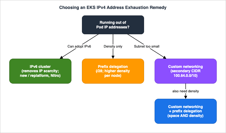
7. Security Groups for Pods and Kubernetes Network Policies
The flat, routable model means that by default every Pod on a node shares the node's security groups — too coarse for workloads with different network trust levels on shared compute. EKS offers two complementary controls: security groups for Pods for the boundary between Pods and AWS resources, and Kubernetes network policies for traffic between Pods.7.1 Security Groups for Pods: Trunk and Branch ENIs
EnablingENABLE_POD_ENI=true on the VPC CNI turns on security groups for Pods. The VPC Resource Controller, which runs on the EKS-managed control plane, then creates a trunk network interface named aws-k8s-trunk-eni on the node and attaches branch network interfaces named aws-k8s-branch-eni to that trunk. A Pod that needs specific security groups is placed on a branch interface carrying exactly those groups.You grant the controller permission by attaching the
AmazonEKSVPCResourceController managed policy to your cluster's IAM role. You then declare which Pods get which security groups with a SecurityGroupPolicy custom resource:apiVersion: vpcresources.k8s.aws/v1beta1
kind: SecurityGroupPolicy
metadata:
name: db-clients
namespace: my-namespace
spec:
podSelector:
matchLabels:
role: db-client
securityGroups:
groupIds:
- sg-0a1b2c3d4e5f6g7h8podSelector or by serviceAccountSelector (one or the other; an empty selector matches all Pods or service accounts in the namespace), and you can list 1 to 5 security group IDs. The specified security groups must allow inbound traffic from the node security group on your probe ports, allow outbound TCP/UDP 53 to CoreDNS, and include whatever rules the Pod needs to reach its peers and the control plane — otherwise matching Pods get stuck in creation. Policies apply only to newly scheduled Pods.7.2 Capacity, max-pods, and Enforcing Mode
Branch interface capacity is additive to the instance's normal secondary-IP limits — for example, anm5.large can carry up to 9 branch interfaces on top of its standard IP capacity. But Pods that use security groups do count toward the node's max-pods, and that value is not auto-adjusted, so you typically need to raise max-pods (or accept fewer Pods than the node could otherwise hold).VPC CNI
1.11 added POD_SECURITY_GROUP_ENFORCING_MODE, which controls both which security groups apply and whether source NAT is used:- strict (the default) — only the branch ENI's security groups are enforced, and source NAT is disabled. This fully isolates Pod traffic, but it also means all Pod traffic — even to the node — enters the VPC network, so NodeLocal DNSCache is not supported, and Pods needing internet must run on private subnets behind a NAT gateway (and you should enable external SNAT:
AWS_VPC_K8S_CNI_EXTERNALSNAT=true). - standard — both the primary ENI's and the branch ENI's security groups apply (traffic must satisfy both). Use this to preserve the client source IP (services with
externalTrafficPolicy: Localon NodePort/LoadBalancer with instance targets), to support NodeLocal DNSCache, and when combining security groups for Pods with Kubernetes network policies.
A mode change affects only newly launched Pods; recycle existing Pods to apply it. Security groups for Pods require Nitro-based instances (the node must be a trunking-compatible type — no
t-family, no Windows), and are not supported on EKS Auto Mode (Section 8). When custom networking and security groups for Pods are used together, the security group from the SecurityGroupPolicy wins over the one in the ENIConfig.Two operational details are easy to miss. First, keep
terminationGracePeriodSeconds non-zero in the Pod spec (the default is 30 seconds): if it is zero, the VPC CNI does not get a chance to tear down the Pod network and the branch ENI is not cleaned up, leaking branch interfaces over time. Second, security groups for Pods also work on AWS Fargate, where each Pod already runs in its own isolation boundary; if you do not attach a SecurityGroupPolicy, Fargate Pods receive the cluster security group by default. On EC2 nodes, the branch-interface model is what lets several Pods on one node each carry a different security group without granting the whole node that access.7.3 Kubernetes Network Policies for East-West Traffic
Security groups for Pods are ideal for controlling access to AWS resources (an RDS database, another VPC service) using your existing security group investment. For controlling traffic between Pods inside the cluster (east-west), use Kubernetes network policies, which the VPC CNI enforces natively (version1.21.0 and later for both standard and admin policies). The network policy controller is enabled through the VPC CNI add-on configuration, and enforcement is implemented with eBPF; the controller materializes a policyendpoints.networking.k8s.aws CRD per policy.The VPC CNI supports two tiers. First, the standard
NetworkPolicy (networking.k8s.io/v1) — namespace-scoped, operating at OSI layers 3 and 4 (IP/port). The example below restricts egress from webapp Pods in the sun namespace to only frontend Pods in another namespace on TCP 8080; all other egress is implicitly denied:apiVersion: networking.k8s.io/v1
kind: NetworkPolicy
metadata:
name: webapp-egress-policy
namespace: sun
spec:
podSelector:
matchLabels:
role: webapp
policyTypes:
- Egress
egress:
- to:
- namespaceSelector:
matchLabels:
name: moon
podSelector:
matchLabels:
role: frontend
ports:
- protocol: TCP
port: 8080ClusterNetworkPolicy (networking.k8s.aws/v1alpha1) — cluster-scoped, for organization-wide rules that namespace teams cannot override. Evaluation order is: all Admin-tier policies first, in priority order (lowest number first), where a Deny action immediately blocks and stops evaluation, an Allow accepts and stops, and a Pass delegates the decision down to the namespace NetworkPolicy tier. Namespace policies can only further restrict what Admin policies allowed or passed — they cannot override an Admin Deny.A few constraints: network policies apply to Pods owned by a Deployment (standalone Pods without
ownerReferences are not covered), only to EC2 Linux nodes (not Fargate or Windows), and to a single IP family per cluster (IPv4 rules are ignored on IPv6 clusters and vice versa). You can combine network policies with both security groups for Pods and prefix delegation/custom networking. In practice: security groups for Pods for the AWS-service boundary, network policies for pod-to-pod segmentation.8. EKS Auto Mode and Managed Pod Networking
EKS Auto Mode shifts data-plane and networking operations to AWS, and it changes how you configure several of the features above. Under Auto Mode, AWS manages the VPC CNI configuration; you do not install or upgrade the networking add-on, and the open-source VPC CNI configuration knobs do not apply. Instead, you customize networking through aNodeClass Kubernetes object — selecting node security groups, controlling subnet placement, setting the node SNAT policy (random or disabled), enabling network policies (including default-deny/allow and network event logging), and isolating Pod traffic onto separate subnets.What Auto Mode does automatically and what it does not support:
- Prefix delegation by default. Auto Mode uses
/28prefixes for Pod networking and maintains a managed warm pool that scales with scheduled Pods. When it detects Pod subnet fragmentation, it falls back to provisioning individual/32secondary IPs. It computesmax-podsper node from the instance type's ENI/IP limits, assuming worst-case fragmentation, and adjusts upward for newer (Nitro v6+) generations with more ENIs/IPs. - IPv6 always caps at 110 Pods per node, provisioning a
/80per node (on a secondary interface when using pod-subnet selectors). - Not supported: security groups for Pods (SGPP) — instead use
podSecurityGroupSelectorTermsin theNodeClass; custom networking viaENIConfig— instead usepodSubnetSelectorTerms; and warm IP / warm prefix / warm ENI / minimum-IP-target configuration. Auto Mode also runs CoreDNS as a node-level system service rather than the traditional deployment (keep the CoreDNS deployment if you mix Auto Mode and non-Auto Mode nodes).
The net effect: Auto Mode gives you the same routable, prefix-dense Pod network with far less tuning, at the cost of the fine-grained
WARM_* control and the ENIConfig/SGPP mechanisms — replaced by NodeClass selectors. If your design depends on ENIConfig-style custom networking or SecurityGroupPolicy, map those to NodeClass equivalents before adopting Auto Mode.The
NodeClass SNAT policy is worth calling out: setting it to disabled stops the node from source-NAT-ing Pod traffic leaving the node, which you want when an upstream firewall or appliance must see real Pod IPs, whereas random preserves the traditional masquerade. Auto Mode can also emit Kubernetes network-policy decisions to an on-node event log, giving you an allow/deny audit trail without running a third-party policy engine.9. Observability and Diagnostics
9.1 Metrics: Watch IP Exhaustion Before It Happens
The VPC CNI exposes Prometheus-format metrics. Deploy the CNI metrics helper to publish them, or use Amazon CloudWatch Container Insights, and alert on:awscni_total_ip_addresses— total IPs allocated to the node.awscni_assigned_ip_addresses— IPs currently assigned to Pods.awscni_available_ip_addresses— IPs free in the warm pool.
The actionable signal is
awscni_available_ip_addresses trending toward zero across nodes in an AZ, or the gap between total and assigned collapsing — both predict the InsufficientFreeAddressesInSubnet and scheduling failures before users notice. Set CloudWatch alarms for "available IPs below my required minimum" and "usage above my threshold."The
cni-metrics-helper is a small deployment that scrapes each node's ipamd metrics and publishes aggregate counts to CloudWatch, so you can alarm at the cluster or AZ level rather than per node. Pair this with a VPC-layer guardrail: enhanced subnet discovery (the ENABLE_SUBNET_DISCOVERY setting on the VPC CNI) lets ipamd allocate ENIs from other tagged subnets in the same VPC and Availability Zone when the node's own subnet is exhausted, buying headroom without re-architecting the cluster. Neither replaces correct subnet sizing, but together they turn silent exhaustion into an early, actionable alarm.9.2 Triaging "Pod Stuck in ContainerCreating"
When a Pod will not start andkubectl describe pod shows FailedCreatePodSandBox, work down this list:- Subnet exhaustion — the node's subnet (or the secondary/
ENIConfigsubnet) has no free addresses. Checkawscni_available_ip_addresses, the subnet's available IP count in the VPC console, and look forInsufficientFreeAddressesInSubnetin events. Fix by freeing or adding address space (prefix delegation, custom networking, IPv6, or a larger subnet), or enable the VPC CNI's enhanced subnet discovery so the CNI can allocate from other subnets in the same VPC and balance across AZs. - Prefix fragmentation — in prefix mode,
InsufficientCidrBlocksin theipamdlogs means no contiguous/28is available; fix with subnet CIDR reservations or a dedicated Pod subnet (Section 4.4). - Security-group misconfiguration — with security groups for Pods, a non-existent security group ID leaves the Pod stuck with
InvalidSecurityGroupID.NotFoundonCreateNetworkInterface; missing CoreDNS (TCP/UDP 53) or probe-port rules cause readiness failures. - Branch ENI / max-pods — with security groups for Pods enabled but
max-podsnot raised, the node hits its Pod ceiling even with branch capacity available.
terminationGracePeriodSeconds: 0 (so the CNI never tore the network down), to branch ENIs left behind when security groups for Pods is misconfigured, or to a node that lost contact with the control plane mid-teardown. Compare awscni_assigned_ip_addresses against the actual running Pod count per node; a persistent gap that does not drain after the 30-second cool-down points at a leak rather than normal warm-pool headroom. The aws-cni-support.sh bundle and the IP-release entries in ipamd.log are the fastest way to confirm it.9.3 Reading ipamd State on the Node
ipamd keeps local introspection state and logs that are the source of truth for IP allocation. The logs live under /var/log/aws-routed-eni/ on the node (ipamd.log and plugin.log). The aws-cni-support.sh script on the node collects this diagnostic bundle. From inside the cluster you can also inspect the moving parts directly:# How many Pods can each node currently allocate?
kubectl get nodes -o custom-columns=NAME:.metadata.name,PODS:.status.allocatable.pods
# Inspect the VPC CNI configuration in effect
kubectl describe daemonset aws-node -n kube-system | grep -E "ENABLE_|WARM_|MINIMUM_|CUSTOM_NETWORK"
# List ENIConfigs (custom networking) and confirm node selection
kubectl get eniconfigs
# Confirm a Pod actually landed on a branch ENI (security groups for Pods)
kubectl describe pod my-pod -n my-namespace | grep -iE "pod-eni|branch"10. End-to-End Architecture Walkthrough
Consider a realistic, constrained scenario: an EKS cluster must run a high density of Pods inside a VPC whose primary10.0.0.0/16 space is already heavily used by other workloads, and one tier of Pods (db-client) must reach an Amazon RDS database while being isolated from the rest of the cluster. This single design combines three of the building blocks above.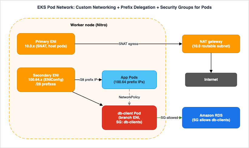
100.64.0.0/16 (RFC 6598) is attached to the VPC. An ENIConfig per AZ points Pods at 100.64 subnets, with ENI_CONFIG_LABEL_DEF=topology.kubernetes.io/zone for automatic per-node selection. ENABLE_PREFIX_DELEGATION=true is set so each secondary ENI carries /28 prefixes. Result: the routable 10.0 space is preserved for nodes, NAT gateways, and load balancers, while Pods scale into the abundant, non-routable 100.64 space at high density. max-pods is recomputed with max-pods-calculator.sh and capped at a compute-sensible value.2. Pod creation flow. When a
db-client Pod is scheduled, the kubelet calls the CNI binary, which asks ipamd for an IP. ipamd draws it from a /28 prefix on a secondary ENI in the 100.64 ENIConfig subnet. Because this Pod matches a SecurityGroupPolicy, the VPC Resource Controller instead places it on a branch ENI off the node's trunk ENI, carrying the db-clients security group. App Pods that do not match the policy get ordinary 100.64 prefix IPs.3. Security — security groups for Pods + network policy. The RDS database's security group allows inbound only from the
db-clients security group, so only branch-ENI Pods with that group can reach the database — not every Pod on the node. A Kubernetes NetworkPolicy restricts east-west traffic so that app Pods can talk only to the services they should. Because we want client source IP preservation and network-policy enforcement alongside security groups, POD_SECURITY_GROUP_ENFORCING_MODE=standard is chosen, and AWS_VPC_K8S_CNI_EXTERNALSNAT is configured to match the egress design.4. Egress. Nodes live in private subnets; Pod traffic to the internet is SNAT'd through the node's primary ENI to a NAT gateway in the routable
10.0 space. In standard enforcing mode, traffic leaving the VPC uses the primary ENI's security groups.Where it breaks (and how to see it):
- If
max-podswas left at the secondary-IP default, the node hits its Pod ceiling even though100.64has abundant IPs —awscni_available_ip_addresseslooks healthy but Pods stayPending. Fix: recomputemax-pods. - If the
100.64subnet is fragmented, prefix allocation fails withInsufficientCidrBlocks— fix with a dedicated Pod subnet or CIDR reservation. - If
strictenforcing mode were used instead, NodeLocal DNSCache would break and the source IP would be lost at the load balancer; if external SNAT were misconfigured,db-clientPods on private subnets could lose internet egress. - IPv6 is not an option to bolt onto this design — it is cluster-wide and mutually exclusive with custom networking. If long-term IPv4 exhaustion is the real concern, the alternative is a new IPv6 cluster, not adding IPv6 here.
This is the Level 400 payoff: each feature is individually simple, but their interactions — which ENI a Pod lands on, which security group applies, where SNAT happens, how
max-pods is counted — determine whether the cluster scales and stays secure.11. Common Pitfalls
- Undersized Pod subnets. Sizing subnets for node count instead of Pod count. Each Pod is a VPC IP; with warm pools, a node reserves more IPs than it has Pods. Size for
nodes * max-pods * warm-pool overhead, and prefer dedicated Pod subnets. Symptom:InsufficientFreeAddressesInSubnet; fix: prefix delegation, custom networking, IPv6, or larger/dedicated subnets. - Prefix fragmentation. Turning on prefix delegation on a busy, fragmented subnet. Symptom:
InsufficientCidrBlocksinipamdlogs and Pods stuck creating; fix: subnet CIDR reservations or a dedicated, prefix-only subnet. - Forgetting to raise max-pods. Enabling prefix delegation or security groups for Pods without recomputing
max-pods. The node silently caps at the secondary-IP value, wasting capacity. Fix:max-pods-calculator.shand update the kubelet/launch template; remember branch-ENI Pods count towardmax-pods. - Misunderstanding SNAT with custom networking and strict mode. Assuming Pods on the secondary CIDR get internet access automatically. In
strictsecurity-groups-for-Pods mode, source NAT is disabled; Pods need private subnets, a NAT gateway, and external SNAT enabled. Symptom: Pod outbound to the internet times out. - VPC CNI version mismatches. Prefix delegation needs
1.9.0+, the largest IPv6 capacity needs1.10.1+, enforcing mode needs1.11+, network policies need1.21.0+. Running an older add-on silently disables features or changes defaults. Never downgrade below1.9.0after assigning prefixes without recreating nodes. Fix: upgrade one minor version at a time and back up settings first. - Mixing IP and prefix assignment on the same node. Transitioning in place rather than with new node groups leads to inconsistent advertised capacity. Fix: create new node groups, drain old ones.
12. Frequently Asked Questions
Why am I running out of Pod IPs even though my nodes have free CPU and memory?
Because the VPC CNI gives each Pod a real VPC IP from the node's subnet, and warm pools reserve extra IPs ahead of demand. Density is bounded by the instance's ENI/IP limits and by subnet size, independent of compute. Checkawscni_available_ip_addresses and the subnet's free address count; the usual fixes are prefix delegation, custom networking, or IPv6.Prefix delegation vs custom networking — which fixes IP exhaustion?
They solve different halves. Prefix delegation increases density per node by giving each ENI slot a/28 (16 IPs) instead of one IP — use it when nodes hit their Pod ceiling but the subnet still has space. Custom networking adds more address space by sourcing Pod IPs from a secondary VPC CIDR (typically RFC 6598 100.64.0.0/10) — use it when the primary subnet is simply too small. For both density and space, combine them. If you can adopt IPv6, it removes the problem entirely.How do security groups for Pods actually work?
SettingENABLE_POD_ENI=true makes the VPC Resource Controller attach a trunk ENI and per-Pod branch ENIs to the node. A SecurityGroupPolicy maps Pods (by label or service account) to 1 to 5 security groups, and matching Pods are placed on a branch ENI carrying those groups, so you can restrict a specific Pod's access to AWS resources (like RDS) without affecting other Pods on the node. They require Nitro instances, count toward max-pods, and have strict/standard enforcing modes that change SNAT and source-IP behavior.Security groups for Pods or network policies — which should I use?
Use security groups for Pods to govern access between Pods and AWS resources (RDS, other VPC services), reusing existing security groups. Use Kubernetes network policies for pod-to-pod (east-west) segmentation inside the cluster. They compose: run them together withPOD_SECURITY_GROUP_ENFORCING_MODE=standard.Should I move to IPv6?
If you are building a new cluster or re-platforming and are bound by IPv4 exhaustion at scale, IPv6 is the cleanest answer — it removes IP scarcity, needs no warm-pool tuning, and keeps IPv4 backward compatibility through an egress-only model. But it is cluster-wide, irreversible, Nitro-only, has no dual-stack, and is incompatible with custom networking — so it is a deliberate up-front decision, not an in-place migration.Does EKS Auto Mode change any of this?
Yes. Auto Mode manages the VPC CNI for you, defaults to prefix delegation, and is configured throughNodeClass instead of CNI environment variables. It does not support security groups for Pods (SecurityGroupPolicy), ENIConfig custom networking, or warm-pool tuning — use podSecurityGroupSelectorTerms and podSubnetSelectorTerms in the NodeClass instead.13. Summary
Amazon EKS networking is shaped by one decision: Pods get real VPC IP addresses through the VPC CNI. Internally, theaws-node DaemonSet splits work between a CNI binary (synchronous Pod wiring) and ipamd (asynchronous ENI and warm-pool management), with max-pods derived from the instance's ENI/IP limits and capped at compute-sensible values. From that foundation, three tools address IPv4 exhaustion — prefix delegation for per-node density, custom networking for additional address space, and IPv6 to remove scarcity entirely — and they compose. Security groups for Pods (trunk/branch ENIs, SecurityGroupPolicy, enforcing modes) and Kubernetes network policies provide complementary segmentation: the former for the AWS-resource boundary, the latter for east-west traffic. EKS Auto Mode wraps most of this in managed defaults configured through NodeClass. The end-to-end design in Section 10 shows the payoff and the failure modes of combining them.To place this in the broader networking picture, see the AWS VPC Connectivity Decision Guide for choosing connectivity between VPCs and services, and the AWS Networking Glossary for terminology. For how serverless compute scales by contrast with Kubernetes Pod density, see the AWS Lambda Concurrency and Scaling Guide, and for using Pods as load-balancer targets, the AWS Elastic Load Balancing Decision Guide.
14. References
- Amazon EKS Best Practices Guide - Amazon VPC CNI
- Amazon EKS Best Practices Guide - Prefix Mode for Linux
- Amazon EKS Best Practices Guide - Custom Networking
- Amazon EKS Best Practices Guide - Security Groups Per Pod
- Amazon EKS Best Practices Guide - Running IPv6 EKS Clusters
- Amazon EKS Best Practices Guide - Optimizing IP Address Utilization
- Amazon EKS User Guide - Assign more IP addresses to nodes with prefixes
- Amazon EKS User Guide - Assign security groups to individual Pods
- Amazon EKS User Guide - Use a security group policy for an Amazon EKS Pod
- Amazon EKS User Guide - Learn about IPv6 addresses to clusters, Pods, and services
- Amazon EKS User Guide - Limit Pod traffic with Kubernetes network policies
- Amazon EKS User Guide - Choose an optimal Amazon EC2 node instance type (How maxPods is determined)
- Amazon EKS User Guide - Enable outbound internet access for Pods (external SNAT)
- Amazon EKS User Guide - VPC Networking and Load Balancing in EKS Auto Mode
- amazon-vpc-cni-k8s - eni-max-pods.txt and CNI configuration (GitHub)
- Amazon EKS pricing
- AWS History and Timeline of Amazon EKS
- AWS History and Timeline of Amazon VPC
- AWS Networking Glossary
- AWS VPC Connectivity Decision Guide
- AWS VPC Network Troubleshooting Guide
References:
Tech Blog with curated related content
Written by Hidekazu Konishi