VPC Design Review Checklist - CIDR, Subnets, Transit Gateway
First Published:
Last Updated:
Table of Contents:
- Why VPC Design Review Matters
- Pre-Design Questions: Workload, Compliance, Scale
- CIDR Planning: Org-Wide Allocation and Future Growth
- Subnet Layout: Public, Private, and Isolated Tiers
- NAT and IGW Placement Decisions
- Connectivity Options: TGW, Peering, VPN, Direct Connect
- Endpoint Strategy: Interface, Gateway, and Resource Endpoints
- Security Group and NACL Layering
- Multi-Region and Multi-VPC Patterns
- Reachability Analysis: Reachability Analyzer and Network Access Analyzer
- VPC Design Review Checklist (Copy-Paste Ready)
- Summary
Why VPC Design Review Matters
Every serious AWS incident I have triaged in the past five years has at least one network-design root cause hiding behind it. Overlapping CIDRs that surface only when two business units finally try to peer their VPCs. NAT Gateways concentrated in a single AZ that take down "multi-AZ" workloads when that AZ has an event. Security groups that look fine in isolation but allow0.0.0.0/0 once you trace the chain through an Application Load Balancer. None of these are exotic; all of them are preventable with a structured review before the VPC is provisioned.This article is the checklist I use during VPC design reviews — both as a reviewer and as someone presenting a design to peers. It covers the full chain of decisions from organization-wide CIDR allocation down to security group layering, with explicit trade-offs at each step. The goal is not to teach you what a VPC is; the goal is to give you a single-page reference that you can paste into a pull request, attach to a design document, or run through with a network architect during a 30-minute review.
The reader I have in mind is a cloud platform engineer or network architect who has already provisioned a few VPCs and is now responsible for either (a) defining the standard pattern that the rest of the organization will follow, or (b) reviewing designs proposed by application teams. If you are landing on AWS for the first time, the official AWS documentation linked at the end of each section is a better starting point.
For deeper coverage of one specific area — private connectivity to AWS services through PrivateLink, Gateway Endpoints, and Resource Endpoints — I refer to my earlier article and use this design-review article as the umbrella that places those endpoint decisions in their wider network context.
AWS PrivateLink and VPC Endpoints Complete Guide - Interface, Gateway, and Resource Endpoint
The structure of the rest of this article mirrors the order I use in real reviews: pre-design questions first, then CIDR, subnets, NAT, connectivity, endpoints, security layering, multi-region, reachability analysis, and finally a copy-paste checklist that consolidates the whole flow.
Pre-Design Questions: Workload, Compliance, Scale
Before any CIDR is drawn, the team proposing the VPC must be able to answer a small set of questions. If they cannot, the review stops here and resumes after they have worked with stakeholders to fill the gaps. Every later decision — CIDR size, subnet count, connectivity option, endpoint strategy — is a function of these answers.The fifteen questions below are the minimum I expect a design document to address. They are intentionally short, so that they can be answered in a one-page table at the top of the document.
* You can sort the table by clicking on the column name.
| # | Question | Why It Matters |
|---|---|---|
| 1 | What is the primary workload type (web app, batch, data lake, ML training, hybrid extension)? | Determines IP density, egress profile, and connectivity needs |
| 2 | What is the expected steady-state and peak host count over the next 24 months? | Drives CIDR size and subnet sizing |
| 3 | Which AWS Regions must this VPC operate in? | Regional vs multi-Region affects connectivity choice (TGW vs Cloud WAN) |
| 4 | How many AZs must the workload survive losing — one or zero? | Determines AZ count (2 vs 3+) and per-AZ NAT topology |
| 5 | Will this VPC connect to on-premises networks via VPN or Direct Connect? | Hard CIDR constraint: must not overlap with corporate space |
| 6 | Will this VPC peer with or share resources across other VPCs (in this org or external)? | Same constraint, plus drives RAM-share and TGW route-table design |
| 7 | What compliance regimes apply (PCI, HIPAA, FedRAMP, ISO 27001, internal frameworks)? | Drives isolated-subnet requirements and flow-log retention |
| 8 | What is the egress profile (heavy egress to internet, AWS services only, on-prem only, none)? | Drives NAT vs Egress-only IGW vs no-egress decisions and endpoint choices |
| 9 | Are public IPs required at all, or is everything fronted by AWS-managed entry points? | Determines whether public subnets are needed or only private/isolated |
| 10 | What is the RTO and RPO for this workload? | Drives multi-AZ NAT, multi-Region replication, failover routing |
| 11 | Who owns the VPC operationally — central network team or application team? | Drives the AWS Resource Access Manager and IAM model |
| 12 | What IaC tool is mandated (CloudFormation, CDK, Terraform)? | Affects how IPAM, route tables, and SCPs are wired up |
| 13 | What is the data-classification level of resources inside the VPC? | Drives isolation, encryption-in-transit, and egress controls |
| 14 | What monitoring and logging are required (VPC Flow Logs, traffic mirroring, GuardDuty)? | Drives subnet-tier separation if traffic mirroring is in scope |
| 15 | Is there an existing organization-wide CIDR registry / IPAM scope to draw from? | If yes, the team must use it; if no, this is a blocker for the org, not the VPC |
If question 15 is "no", the VPC review is paused and the question is escalated to the platform team. Designing a new VPC without an organization-wide CIDR plan is exactly how overlap incidents are born.
The answers to these questions are not just for the reviewer — they are the source of truth that the design will be measured against in every subsequent section. I keep a copy of the table in the design document and refer back to it whenever a later decision contradicts an earlier answer.
A practical design-document template
The questions above turn into a one-page design-document header that the design-review meeting opens with. The fields below are the minimum:| Field | Example value | Notes |
|---|---|---|
| Workload type | E-commerce web tier with Aurora PostgreSQL | Free-form, but specific |
| Account ID(s) | 123456789012 (prod), 234567890123 (non-prod) | One or more |
| Regions | us-east-1 (primary), us-west-2 (DR) | Order matters |
| AZ count per Region | 3 (us-east-1), 2 (us-west-2) | Justify any deviation from 3 |
| Expected hosts at peak | ~600 ENIs (300 ECS tasks, 6 RDS, 12 ALB ENIs, ...) | Per-VPC |
| Hybrid connectivity | VPN (active) + DX (planned Q3) | "None" is a valid value |
| Compliance | PCI-DSS in-scope for the data tier | Affects logging and isolation |
| RTO / RPO | RTO 60 min, RPO 5 min | Drives multi-AZ NAT, multi-Region replication |
| Owner | Platform Networking Team (alias aws-net) | The team that owns ongoing operations |
| IaC | Terraform 1.6, modules in infra-net repo | Affects how IPAM and TGW are wired up |
| Data classification | Confidential (orders), Public (catalog images) | Drives isolated-tier requirements |
| Logging | Flow Logs → central log archive (account 999...) | Must reference the central pattern |
| Existing IPAM scope | org-private/us-east-1/prod | Pull this from the network team's IPAM |
When the design document opens with this table, the rest of the review proceeds quickly: every decision the rest of the document makes can be checked against this header. When the table is missing or partially filled, the review becomes an ad-hoc Q&A and frequently has to be rescheduled.
CIDR Planning: Org-Wide Allocation and Future Growth
Sizing a single VPC's CIDR is easy. Sizing every VPC in an organization so that they will never overlap, will leave room to grow, and will summarize cleanly on a route table is hard, and is the most common point of failure I see in reviews.The pattern that has held up across every organization I have worked with is a three-level hierarchy: a top-level reservation covering the whole organization, regional sub-allocations inside it, and per-VPC blocks carved out of each region. Amazon VPC IP Address Manager (IPAM) implements this hierarchy directly and enforces it programmatically.
A reference allocation
For a medium-large organization that uses AWS in three Regions, the following allocation gives nine years of headroom and can be summarized on a single route entry per region:Top-level reservation (org-wide): 10.0.0.0/8 (16,777,216 addresses)
Region pool: us-east-1 10.0.0.0/12 (1,048,576 addresses)
Production: 10.0.0.0/14
Pre-production: 10.4.0.0/14
Sandbox: 10.8.0.0/14
Network services (TGW, etc.): 10.12.0.0/14
Region pool: ap-northeast-1 10.16.0.0/12
Production: 10.16.0.0/14
...
Region pool: eu-west-1 10.32.0.0/12
...
Reserved for future Regions: 10.48.0.0/12 ... 10.240.0.0/12Each VPC is then allocated a
/16 (or smaller) from the appropriate environment pool. A /16 gives 65,536 addresses — enough for the canonical three-tier × three-AZ layout (nine subnets) with substantial growth room.If your organization is smaller, the same hierarchy with a
10.0.0.0/12 top-level (1 M addresses) usually suffices. If you cannot use 10.0.0.0/8 because on-premises already owns part of it, switch to 172.16.0.0/12 and apply the same hierarchy.Subnet sizing inside a /16 VPC
A balanced default for a three-AZ × three-tier VPC inside a10.x.0.0/16:| Tier | AZ-a | AZ-b | AZ-c | Notes |
|---|---|---|---|---|
| Public (ALB, NAT GW, bastion) | 10.x.0.0/24 | 10.x.1.0/24 | 10.x.2.0/24 | 251 usable addresses each |
| Private application | 10.x.16.0/20 | 10.x.32.0/20 | 10.x.48.0/20 | 4,091 usable each, sized for containers |
| Isolated data | 10.x.64.0/24 | 10.x.65.0/24 | 10.x.66.0/24 | RDS / ElastiCache / OpenSearch |
| TGW attachment | 10.x.255.0/28 | 10.x.255.16/28 | 10.x.255.32/28 | One small subnet per AZ for TGW ENIs |
| Reserved | 10.x.128.0/17 | — | — | Future expansion (new tiers, EKS node groups, etc.) |
Three sizing rules I always enforce in review:
The first rule is that AWS reserves five IP addresses in every subnet. A
/28 therefore yields only 11 usable addresses, not 16. Anyone proposing a /28 for application workloads is told to redo the math.The second rule is that subnet sizes must be consistent across AZs. If
10.x.16.0/20 is the application subnet in AZ-a, then AZ-b and AZ-c get 10.x.32.0/20 and 10.x.48.0/20, not arbitrary other prefixes. Inconsistent sizing makes route tables harder to read and traps people during incident response.The third rule is that you must reserve at least 25% of the VPC's address space for future expansion. Container platforms in particular consume IPs faster than people predict (every pod gets an IP under the AWS VPC CNI), and renumbering a VPC after the fact is one of the most expensive operations in AWS.
What IPAM gives you
If you operate more than a handful of VPCs, IPAM is no longer optional. It centralizes the hierarchy above into AWS, prevents overlap automatically, supports allocation rules so that only resources with specific tags can draw from a pool, and (in recent releases) can manage subnet CIDRs as well as VPC CIDRs. For an organization that has standardized on AWS Organizations + Control Tower, IPAM is the natural source of CIDRs for the Account Factory pipeline.The IPAM controls I always check during review:
The first control is that IPAM is delegated to a dedicated network-administration account, not the management account. The management account should not be a day-to-day operations account.
The second control is that allocation rules require specific tags (for example,
Environment=Production) so that no one can allocate from the production pool by mistake.The third control is that an SCP enforces the use of IPAM — explicitly denying
ec2:CreateVpc actions that do not use an IPAM pool ID — so application teams cannot bypass the system.IPAM allocation rules in practice
The control points worth enabling on every IPAM pool are below. Each one corresponds to a class of mistake I have seen in incident postmortems.The first control is
auto-import, which lets you bring existing CIDR allocations under IPAM management without renumbering. Without it, the migration to IPAM is so painful that teams often stop halfway and accept long-term inconsistency.The second control is the allocation minimum and maximum — the smallest and largest CIDR an allocation request can take. For a production pool, a minimum of
/24 and a maximum of /16 matches the canonical sizing. Anyone requesting a /27 is almost certainly making a sizing mistake; anyone requesting a /12 is almost certainly making a different sizing mistake.The third control is the default netmask length, which is the size IPAM hands out when the requester does not specify a size. Setting this to
/16 makes the standard request explicit and any deviation a deliberate choice.The fourth control is allocation rules based on tags. A pool can be configured to refuse allocations from resources that lack a specific tag — for example, the production pool refuses allocations unless the requesting VPC has
Environment=Production. This catches sandbox VPCs trying to allocate from the production pool.The fifth control is the locale — the AWS Region the pool is bound to. A pool bound to
us-east-1 cannot be used to allocate CIDRs for VPCs in other Regions. This is the simplest and most effective control against accidental cross-Region misallocation.The sixth control is monitoring. IPAM publishes utilization metrics for every pool to CloudWatch. Set an alarm at 70% utilization and another at 90% so that the network team has runway to provision additional pools before the regional space is exhausted.
Why the registry must be enforced
A CIDR registry that is documentation-only is not a registry — it is a wiki page. Two failure modes recur:The first failure mode is allocation drift. Two teams independently allocate the same CIDR, both think they are the rightful owner, and the conflict surfaces a year later when one of them needs to peer or share the network. By that point the cost of resolving the conflict (renumber one VPC) is high enough that the conflict is just… tolerated, and the architecture quietly contains a foreign object until something breaks.
The second failure mode is silent expansion. A team that needs more IPs adds a secondary CIDR to their VPC and picks one from the next visually-empty space in the registry. That space turns out to be reserved for a future Region or a future business unit, and the conflict resurfaces when that future expansion happens.
The defense in both cases is to make IPAM the only allowed CIDR source. An SCP that denies
ec2:CreateVpc and ec2:AssociateVpcCidrBlock actions when they do not reference an IPAM pool ID closes both failure modes at once. The cost is that occasional emergency CIDR work goes through an exception process, which in my experience is exactly what the network team wants.CTA: Subnet math, before you commit
Before you finalize any VPC's CIDR layout, run the subnet plan through a calculator. The site-internal tool linked below converts an arbitrary IP range into the smallest set of CIDR blocks and is the fastest way to sanity-check a hand-drawn plan.IP Range to CIDR Tool
Subnet Layout: Public, Private, and Isolated Tiers
Once the CIDR is fixed, the next decision is how to slice the VPC into subnets. The pattern that survives the largest number of workloads is the three-tier split: public for things that need direct internet exposure, private for application compute, and isolated for data stores.A subnet is "public" only because its associated route table contains a
0.0.0.0/0 route to an internet gateway. There is no flag set at subnet-creation time that makes a subnet public. The same subnet becomes "private" the moment that route is removed. This is worth restating because it has direct security implications: a misplaced route table association can silently expose a database tier.The canonical three-tier x multi-AZ layout
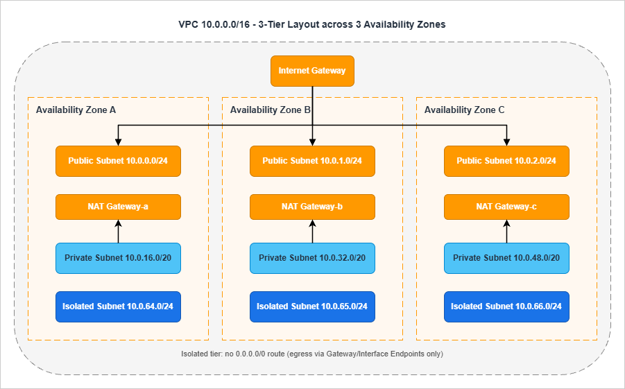
/24 because the workload there is sparse: a NAT Gateway uses one ENI, an ALB uses one ENI per AZ.The private tier hosts the application compute. This is where most of the IP consumption happens, particularly with container workloads. EKS pods, ECS tasks on Fargate, and Lambda functions in a VPC all consume private subnet IPs. Sizing a
/20 per AZ (4,091 usable addresses) is a safe default for container-heavy workloads; a /24 is acceptable for VM-only patterns.The isolated tier hosts data stores. Resources here have no route to
0.0.0.0/0 at all — not via NAT, not via IGW. Outbound calls to AWS services happen through Gateway Endpoints (S3, DynamoDB) or Interface Endpoints (everything else). RDS, ElastiCache, OpenSearch, and any persistent data store with regulatory implications belong here. A /24 per AZ is generally enough.Subnet count math
For the canonical layout above, the math is:Tiers (3) × AZs (3) = 9 subnetsAdd one TGW-attachment subnet per AZ (a
/28 is enough for the TGW ENIs), and an EKS-control-plane subnet per AZ if EKS is in scope, and the count rises to 12 or 15. Always plan for these auxiliary subnets up front; adding them later means provisioning route tables, NACLs, and security groups all over again.Subnet-layout review questions
I always ask the four questions below in review:| # | Question | Pass Criterion |
|---|---|---|
| 1 | Is every tier present in every in-scope AZ? | Three subnets per tier when three AZs are in scope, two when two are |
| 2 | Are subnet sizes identical across AZs within a tier? | /20 in AZ-a means /20 in AZ-b and AZ-c |
| 3 | Are there separate route tables per tier (not per subnet)? | Three route tables (public, private, isolated), each associated with three subnets |
| 4 | Is the isolated tier's route table free of any 0.0.0.0/0 entry? | Confirmed by inspecting the route table after creation |
The third question is the one teams get wrong most often. It is tempting to create one route table per subnet, but doing so multiplies the number of objects you need to keep consistent. Three route tables per VPC, one per tier, scales much better.
EKS and container-platform considerations
Container platforms have IP-density characteristics that change subnet sizing. The two patterns below cover the common cases:For EKS with the standard AWS VPC CNI, every pod gets a routable IP from the worker-node's subnet. A node running 30 pods consumes 30 IPs in addition to the node's own IP. For a cluster running 100 nodes at 30 pods each, that is 3,100 IPs from the application subnets — which is why container-heavy workloads need
/20 application subnets, not /24. If your cluster will use the AWS VPC CNI in custom networking mode (where pods are assigned IPs from a separate "secondary CIDR" added to the VPC), allocate that secondary CIDR from a dedicated IPAM pool to keep it auditable.For ECS on Fargate, every task uses one ENI in the task's subnet. Density is roughly one ENI per task, similar to a small EC2 instance. Subnet sizing of
/22 or /20 per AZ is appropriate for production fleets. Watch the ec2:NetworkInterface quota at the account level; high-density Fargate workloads are the most common reason that account hits the ENI quota ceiling.For both platforms, a separate "service" subnet for AWS Load Balancer Controller-provisioned NLBs is sometimes useful. The NLB ENIs go in the public tier and consume IPs there; sizing the public subnets
/24 is generally enough, but if you front many services with separate NLBs, plan for it.Subnet flagging: auto-assign public IP
Theauto-assign public IPv4 address setting on a subnet is one of the most dangerous toggles in the VPC console. It causes any ENI created in that subnet to get a public IP automatically, which silently exposes anything that lands there to the internet (subject to SG rules).The rule I enforce is simple: this toggle is off everywhere except the public-tier subnets, and even there it is set explicitly per-resource via launch templates rather than as a subnet default. The reason is that subnet defaults survive long after the original use case — you end up with a "public" subnet that is being reused for something that should never have had public IPs.
NAT and IGW Placement Decisions
NAT Gateway placement is where availability and cost diverge most visibly. The cheapest answer is one NAT Gateway centralized somewhere; the most resilient answer is one NAT Gateway per AZ; the right answer depends on the workload's RTO.The four options on the table
* You can sort the table by clicking on the column name.| Option | Resilience | Cross-AZ Cost | Operational Cost | When To Use |
|---|---|---|---|---|
| Single NAT GW (one AZ) | Lowest — AZ outage breaks all egress | High — all other AZs cross zones | Lowest | Dev/sandbox only |
| One NAT GW per AZ | Highest | None — traffic stays in-AZ | Highest | Production; default recommendation |
| Centralized NAT in egress VPC | Medium — depends on egress VPC topology | Inter-VPC + inter-AZ | Medium | Multi-VPC orgs that want centralized egress filtering |
| NAT Instances (self-managed) | Depends on Auto Scaling Group | None | Medium — you manage the AMI and scaling | Niche; almost always wrong now |
For production workloads, the default I recommend is one NAT Gateway per AZ. The only scenario where I deviate is when the organization has standardized on a centralized egress VPC for outbound traffic inspection — in which case the NAT lives in that egress VPC and the spokes attach via TGW.
Egress-only IGW for IPv6
If the workload uses IPv6 and you need outbound-only internet access, the right primitive is an Egress-only Internet Gateway, not a NAT Gateway. NAT does not apply to IPv6 in AWS; the address-translation problem that NAT solves does not exist with global IPv6 addresses. The Egress-only IGW provides the equivalent "outbound but not inbound" semantic at no charge per gateway-hour.Common NAT misconfigurations
The five misconfigurations I see most often during review:The first is a single NAT Gateway servicing a "multi-AZ" workload. The team usually says "we wanted to save the NAT Gateway hourly cost" — which is exactly what they will not be saying when their workload is offline because the NAT's AZ had an event.
The second is NAT Gateways placed in private subnets. NAT Gateways must live in a public subnet (a subnet with a
0.0.0.0/0 route to the IGW). Placing them in a private subnet means they have no path to the internet themselves, and traffic silently fails.The third is private subnets routing
0.0.0.0/0 to the IGW directly. This converts the private subnet into a public subnet by definition. It is usually a copy-paste error from a public route-table template.The fourth is private subnets pointing to a NAT Gateway in a different AZ when there is one available in their own AZ. This works, but it incurs cross-AZ data-transfer costs on every egress packet and reintroduces the AZ-outage failure mode the team thought they had eliminated.
The fifth is forgetting to enable VPC Flow Logs on the public-tier subnets. Flow Logs in the public tier are the only ground truth for which clients are using the NAT and how much data they are pushing through it — both of which matter for cost reviews and incident investigation.
Connectivity Options: TGW, Peering, VPN, Direct Connect
Connectivity is where small organizations and large organizations diverge fastest. Two VPCs need a peering connection. Twenty VPCs need a Transit Gateway. A hundred VPCs across multiple Regions need a Cloud WAN.The five options
The connectivity decision splits into five primitive options that can be combined:The first is VPC Peering. It is point-to-point, non-transitive, and free of per-hour charges (you pay only for cross-AZ data transfer). It scales as
n × (n-1) / 2, which means twenty VPCs require 190 peering connections — an unmanageable number. Use peering only for small numbers of VPCs that need direct, dedicated connectivity.The second is AWS Transit Gateway (TGW). A TGW is a regional hub-and-spoke router that supports VPCs, VPN connections, Direct Connect Gateway attachments, TGW-to-TGW peering, and Connect attachments for SD-WAN appliances. It scales to thousands of VPCs in a Region. It is shared across accounts with AWS Resource Access Manager (RAM).
The third is Site-to-Site VPN. This is the canonical hybrid-connectivity primitive when Direct Connect is unavailable, too expensive, or being used as a backup path. VPN connections terminate either on a Virtual Private Gateway (one VPC) or on a Transit Gateway (many VPCs). Always provision two tunnels per VPN connection for resilience — AWS provides this automatically — and use BGP for dynamic routing.
The fourth is AWS Direct Connect (DX). Dedicated network connections, typically 1 Gbps, 10 Gbps, or 100 Gbps, with consistent latency and no public-internet path. Used in production hybrid setups. Must be deployed with redundancy (multiple connections to multiple Direct Connect locations); a single DX is a single point of failure. Direct Connect Gateway is the construct that lets one DX connect to VPCs in multiple Regions.
The fifth is AWS Cloud WAN. Cloud WAN is a global, policy-driven network that AWS implements on your behalf. You write a JSON core-network-policy document; AWS provisions the equivalent of a TGW in each Region you specify and connects them automatically with built-in segmentation. Cloud WAN is the right choice when you operate in many Regions and want intent-driven configuration. Cloud WAN can also peer with existing TGWs (federation), which is the common migration path.
Hub-and-spoke with Transit Gateway
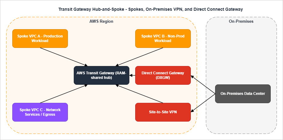
/28 TGW-attachment subnet per AZ. The TGW routing tables segment traffic: production VPCs in one routing table, non-production in another, and a separate one for the egress / inspection VPC.Routing tables and segmentation
A common mistake is to use a single TGW route table and rely on subnet-level controls for segmentation. The right pattern is at least three TGW route tables:The first is the production route table, associated with all production VPC attachments and the on-premises attachments that need to reach production.
The second is the non-production route table, associated with development and staging VPCs. It propagates routes only to non-production destinations and has explicit blackhole entries for production CIDRs to make the segmentation auditable.
The third is the network-services route table, used by the egress VPC and inspection VPC. It propagates routes to all spokes (so that return traffic finds its way back) but is itself the only route table containing
0.0.0.0/0 pointing to the egress VPC.VPN and Direct Connect details that get missed
The four details below come up in nearly every hybrid review:The first detail is BGP versus static routing. Always use BGP for production hybrid connectivity (VPN or DX). Static routes work but they require manual updates whenever either side changes, and the failure mode — black-holed traffic that nothing notices — is among the worst. BGP advertises route changes automatically and the BGP session itself is the heartbeat that surfaces a broken tunnel.
The second detail is ECMP for Site-to-Site VPN on a Transit Gateway. A single VPN connection has two tunnels (1.25 Gbps each); enabling ECMP on the TGW lets you scale by adding additional VPN connections, and the TGW will load-balance across all the tunnels. ECMP requires that the VPN attachments use BGP-based dynamic routing — static-routed VPN attachments are not eligible. Without ECMP you cap out at one connection's throughput regardless of how many connections you provision.
The third detail is Direct Connect redundancy. A single DX connection is a single point of failure — the SLA is per-connection, not per-deployment. Production deployments use either (a) two DX connections to two different Direct Connect locations or (b) one DX with a Site-to-Site VPN as the backup. AWS publishes "DX Resiliency Toolkit" with three reference designs (Maximum Resiliency, High Resiliency, Development) that map directly to these patterns.
The fourth detail is the Direct Connect Gateway. A single DX connection to a single Direct Connect location can connect to VPCs in multiple Regions through a Direct Connect Gateway. This is how you avoid provisioning a separate DX per Region. DXGW is a routing construct, not a data-plane element — it does not have a physical presence.
TGW attachment subnet sizing
The TGW-attachment subnet is where the TGW places its ENIs, one per AZ per attachment. A/28 is generally enough (11 usable IPs is more than the TGW will ever use), but a /27 or /26 is reasonable if you anticipate adding additional attachments to the same VPC and want headroom.The attachment subnet's NACL must be permissive in both directions for the TGW to function correctly. A common error is to apply restrictive NACLs to attachment subnets thinking they are "internal infrastructure"; the result is asymmetric routing where outbound traffic works but the return path is dropped.
When to use what
* You can sort the table by clicking on the column name.| Scenario | Recommended Primitive |
|---|---|
| 2–3 VPCs, single Region, ad-hoc connectivity | VPC Peering |
| 4+ VPCs, single Region | Transit Gateway |
| Many VPCs, multiple Regions, you want to manage routing yourself | Multiple TGWs + TGW-to-TGW peering |
| Many VPCs, multiple Regions, you want policy-driven config | Cloud WAN |
| Existing TGW investment + global expansion | TGW + Cloud WAN federation |
| Hybrid with high bandwidth + low latency | Direct Connect |
| Hybrid backup or low-volume hybrid | Site-to-Site VPN |
| Branch offices with SD-WAN appliances | TGW Connect or Cloud WAN Connect |
| Centralized egress filtering for many VPCs | Egress VPC behind TGW |
Endpoint Strategy: Interface, Gateway, and Resource Endpoints
For traffic that stays within AWS, the right tool is a VPC endpoint. Endpoints replace internet egress with a private path, eliminate NAT Gateway data-processing charges for the in-scope traffic, and let you attach an endpoint policy to scope access.There are three endpoint types, each with a specific use case:
| Endpoint Type | Scope | Cost Model | When To Use |
|---|---|---|---|
| Gateway Endpoint | S3 and DynamoDB only | Free; route-table entry | Always for S3 and DynamoDB |
| Interface Endpoint (PrivateLink) | Most other AWS services + your own services | Per-hour + per-GB | Granular service-by-service privatization |
| Resource Endpoint (VPC Lattice) | Specific cross-VPC resources (RDS, etc.) | Per-hour + per-GB | Cross-VPC private access without full endpoint sprawl |
The endpoint-strategy questions I check in review are the standard four:
The first is whether Gateway Endpoints exist for S3 and DynamoDB. They are free and they avoid NAT data-processing charges. Not having them is almost always a cost-and-security regression.
The second is whether Interface Endpoints exist for the services that the workload actually calls. Common candidates are Secrets Manager, Systems Manager (SSM), KMS, ECR API and DKR, CloudWatch Logs, STS. Provisioning Interface Endpoints for services the workload does not use is wasted hourly charges, so this is not a "more is better" question.
The third is whether endpoint policies are in place. By default, an Interface Endpoint allows full access to the service. An endpoint policy restricts which principals and which resources can be reached through the endpoint — for example, "only roles in this account can use this endpoint, and only to access buckets owned by this account." This is the privilege boundary that endpoints add on top of IAM.
The fourth is whether private DNS is enabled. Private DNS (or Route 53 Profile) makes the public service hostname resolve to the endpoint ENI inside the VPC. Without it, applications need to use the endpoint-specific DNS name, which usually means code changes — rarely worth the friction.
For the deep dive on each endpoint type, including endpoint policies, cross-Region PrivateLink, and the centralized-endpoints-VPC pattern, see the dedicated guide.
AWS PrivateLink and VPC Endpoints Complete Guide - Interface, Gateway, and Resource Endpoint
Security Group and NACL Layering
Security Groups (SG) and Network ACLs (NACL) operate at different layers and have different semantics. Confusing them is one of the most reliable ways to either ship an insecure VPC or paint yourself into a corner where legitimate traffic is dropped.The role split
| Property | Security Group | Network ACL |
|---|---|---|
| Layer | ENI / instance | Subnet |
| State | Stateful | Stateless |
| Default action | Implicit deny | Explicit deny (last rule) |
| Rule order | All rules evaluated | First match wins |
| Allow only | Yes | Allow + Deny |
| Where applied | Each ENI explicitly | Each subnet automatically |
In practice, Security Groups are the primary control. You define one SG per role (
alb-sg, app-sg, db-sg) and reference one SG from another rather than referencing CIDRs. NACLs are a coarse second layer that catches gross errors at the subnet boundary — they should not be your day-to-day control.Defense-in-depth pattern
For a three-tier web application, the canonical layering is:The first layer is at the ALB. The ALB SG allows inbound 443 from
0.0.0.0/0 (or a known CDN range), nothing else.The second layer is at the application tier. The app SG allows inbound 8080 (or whatever the application port is) only from the ALB SG. It does not allow any traffic from the internet directly.
The third layer is at the data tier. The database SG allows inbound 3306 (or 5432, etc.) only from the app SG. It does not allow connections from the ALB tier or from the internet.
The fourth layer, NACLs, is intentionally permissive: allow all traffic in both directions. The exception is when a compliance regime (PCI, FedRAMP) requires explicit subnet-level deny rules for known-bad ports; in that case, deny rules are added at the NACL but allow rules remain wide open.
The fifth layer is endpoint policies on Interface Endpoints, as covered in the previous section. They restrict which principals can reach AWS services through the endpoint — an authorization layer on top of network reachability.
Five SG/NACL anti-patterns
The first anti-pattern is referencing CIDRs from another VPC in a security group rule. This works, but it locks you into that VPC's CIDR. The moment the peer VPC is rebuilt with a different CIDR (or a new spoke is added), the rule must be updated. Reference SGs from peered VPCs instead, using SG-to-SG references where the peering relationship supports it.The second anti-pattern is using NACLs as the primary access control. NACLs are stateless and operate on connection establishment, not on connection state. Implementing fine-grained access control via NACLs means tracking ephemeral port ranges in deny rules, which is brittle and operationally painful.
The third anti-pattern is overlapping
0.0.0.0/0 allow rules across multiple SGs attached to the same ENI. SG rules are additive, so the moment any SG attached to an ENI allows 0.0.0.0/0, that traffic is allowed regardless of what other SGs say. Audit attached SGs as a set, not individually.The fourth anti-pattern is leaving the default security group permissive. The VPC default SG allows all egress and allows ingress from itself. Many teams attach the default SG to ENIs "temporarily" and then never remove it. The cleanup move is to strip all rules from the default SG immediately after VPC creation so that an accidental attachment causes a noisy failure rather than a silent overshare.
The fifth anti-pattern is using
0.0.0.0/0 egress on the database tier "for yum" or "for OS updates". Database hosts that need to reach the internet are a sign that the patching pipeline is wrong. Patch images upstream (golden AMI) or proxy patch traffic through a managed update mechanism; do not punch a hole in the data tier.SG references across VPC peering
When two VPCs are connected via a peering connection, security groups in either VPC can reference security groups in the other — the same SG-to-SG reference pattern that works inside a VPC. This is a strong simplification: instead of maintaining CIDR allowlists that track the peer VPC's CIDR, you reference the peer VPC's SG ID directly.This pattern originally worked only for same-Region peering. AWS later extended cross-VPC security group references to Inter-Region VPC Peering and to Transit Gateway peering attachments, so the SG-to-SG model now scales across Regions as well — provided the feature is explicitly enabled on the peering attachment and the referenced security group is in an account and Region that the local VPC has visibility into. For traffic where you do not want a peering relationship at all, AWS PrivateLink remains the right primitive: terminate the connection at an Interface Endpoint and apply SG rules at the endpoint ENI in each Region.
Egress SGs and explicit egress rules
The default SG configuration allows all egress to0.0.0.0/0. For most workloads this is fine; for compliance-sensitive workloads it is unacceptable. The pattern for explicit egress control is to remove the default 0.0.0.0/0 egress rule and add narrow rules that reference the destinations the workload actually needs — SG references for in-VPC destinations, prefix lists for AWS service CIDRs (S3, DynamoDB), and explicit CIDRs for whitelisted external destinations.Prefix lists are the right primitive for AWS service CIDRs. Each AWS service publishes a managed prefix list (for example,
com.amazonaws.us-east-1.s3) that contains the current set of CIDRs. Reference the prefix list in your SG rule and the rule auto-updates when AWS adds or removes CIDRs — you no longer track this by hand.Multi-Region and Multi-VPC Patterns
Single-region designs hit different limits than multi-region designs. The patterns below cover the common steady-state architectures.Multi-Region with TGW peering
Two TGWs in two Regions can be peered directly. Each TGW continues to handle its Region's spokes; cross-Region traffic flows over the peering connection. This is the lowest-effort multi-Region pattern, but the route tables are not auto-synchronized — you maintain them per Region.Multi-Region with Cloud WAN
Cloud WAN provides a single core-network-policy document that defines all Regions, all segments, and all routing. AWS provisions a Core Network Edge (CNE) in each Region you list, and the CNEs are connected automatically. Cross-Region routing is dynamic and managed by Cloud WAN.The trade-off is that Cloud WAN is policy-driven: you give up imperative control of route tables in exchange for declarative segmentation. Most organizations find this a positive trade-off once they pass roughly five Regions. Below five Regions, multiple TGWs with peering is usually simpler.
Centralized egress VPC
A centralized egress VPC is a "network-services" VPC that owns the NAT Gateways and (often) AWS Network Firewall for the entire organization. Spoke VPCs have no NAT of their own; their default route points across TGW to the egress VPC, which forwards to NAT and then to the internet.The trade-off is data transfer: every egress packet now traverses TGW (paying inter-VPC processing charges) on top of the NAT Gateway data-processing charge. The benefit is centralized inspection — one place to enable Network Firewall, log all egress, and apply DNS Firewall.
For organizations with serious compliance or threat-hunting requirements, the centralized egress pattern is worth the cost. For the rest, per-VPC NAT is typically cheaper and operationally simpler.
Multi-VPC patterns inside a single account
Even within a single AWS account, multiple VPCs are sometimes appropriate: a production VPC, a non-production VPC, and a shared-services VPC. The cost of running multiple VPCs is small; the benefit is cleaner blast-radius separation.The constraints to remember when going multi-VPC: VPCs do not share security groups, route tables, or NACLs. Resources in different VPCs talk to each other over peering, TGW, or PrivateLink. There is no concept of "shared VPC" inside a single account except via the AWS Resource Access Manager and shared subnets.
Reachability Analysis: Reachability Analyzer and Network Access Analyzer
The two tools below shorten the time-to-root-cause for connectivity issues from hours to minutes. Both are worth their per-analysis cost in any incident.VPC Reachability Analyzer
Reachability Analyzer performs static analysis of your VPC configuration. You specify a source (an ENI, a subnet, an internet gateway) and a destination (another ENI, an IP, a port), and the tool walks every relevant route table, security group, NACL, and routing component to determine whether a path exists.If a path exists, Reachability Analyzer renders the full hop-by-hop chain — useful for confirming that a complex topology behaves as designed. If no path exists, the tool returns the specific component that blocks the path along with an explanation code (for example,
ENI_SG_RULES_MISMATCH, NO_MATCHING_ROUTE, BLACK_HOLE, or NETWORK_INTERFACE_HAS_NO_PUBLIC_IP_ADDRESS).Cross-account analysis is supported through trusted access in AWS Organizations: register member accounts as delegated administrators and a single user can run analyses spanning the whole organization.
The typical use cases I rely on:
The first use case is post-deployment verification. Run an analysis from a known source to a known destination and confirm the path is what the design says it should be. CI/CD systems can call
aws ec2 create-network-insights-path to make this part of the deployment pipeline.The second use case is incident triage. When a workload reports "I cannot reach this database", Reachability Analyzer answers in 30 seconds whether the problem is configuration (route, SG, NACL) or something else (application, DNS, capacity).
The third use case is migration validation. When moving a workload from one VPC to another, run paired analyses on the old and new networks to confirm that the new topology preserves the same reachability.
A concrete CLI invocation that runs an analysis between two ENIs on TCP/443 is short enough to live in a runbook:
aws ec2 create-network-insights-path \
  --source eni-0abc123def456 \
  --destination eni-0xyz789ghi012 \
  --protocol tcp \
  --destination-port 443

aws ec2 start-network-insights-analysis \
  --network-insights-path-id nip-0abc123def456
The result of
describe-network-insights-analyses carries a NetworkPathFound boolean and, when the path is blocked, an Explanations array with explanation codes such as ENI_SG_RULES_MISMATCH or NO_MATCHING_ROUTE. Wiring this into a CI/CD step is straightforward: provision the topology, run the analysis, fail the build if NetworkPathFound is false.VPC Network Access Analyzer
Network Access Analyzer is the inverse tool. Instead of "can A reach B?", it answers "what can reach B that should not?" or "what paths exist that bypass our intended controls?"You define a Network Access Scope describing the access pattern you want to validate (or invalidate), and the tool returns every path in your VPCs that matches the scope. Typical scopes:
- All paths from internet sources that bypass the intended firewall or inspection point.
- All paths to the database tier from sources outside the application tier.
- All paths from the management VPC to production VPCs.
In practice, Network Access Analyzer is the tool I run before any major topology change ships and again afterwards as a regression check. It answers questions that a handful of Reachability Analyzer runs cannot answer comprehensively.
Region availability for both tools has expanded over time. Confirm the current Region list against the official AWS Reachability Analyzer and Network Access Analyzer service pages before relying on either in a new Region or in AWS GovCloud.
VPC Design Review Checklist (Copy-Paste Ready)
The checklist below is the consolidation of every section above. I keep it pinned in the design-review template; reviewers tick each item before approving the design. The intent is that any item left unticked must have an explicit, documented reason in the design document.Pre-Design
- All fifteen pre-design questions (workload type, growth, AZs, compliance, RTO/RPO, etc.) are answered explicitly in the design document
- The design document references an organization-wide CIDR plan or IPAM scope as the source of truth
- Owner of the VPC (network team or application team) is identified in the document
- Compliance regime is stated, and its implications for subnet isolation and flow-log retention are addressed
- Hybrid connectivity intent (VPN, DX, none) is stated up front
CIDR
- VPC CIDR is allocated from the IPAM hierarchy — not hand-picked
- CIDR does not overlap with on-premises or any peered VPC
- CIDR has at least 25% reserved space for future expansion
- Subnet sizing accounts for the five AWS-reserved IPs per subnet
- Subnet sizes are consistent across AZs within the same tier
- If the workload is container-heavy, application subnets are at least
/20 - Auxiliary subnets (TGW attachment, EKS control plane, etc.) are planned at design time, not added later
- An SCP enforces use of IPAM at the organization level
Subnet Layout
- Three tiers (public, private, isolated) are explicitly identified in the design
- Every tier exists in every in-scope AZ
- One route table per tier (not per subnet) is used
- Public-tier route table contains a
0.0.0.0/0route to the IGW - Private-tier route table contains a
0.0.0.0/0route to the per-AZ NAT Gateway - Isolated-tier route table contains no
0.0.0.0/0route — only intra-VPC and endpoint routes - If EKS is in scope, dedicated subnets exist for the control plane and the data plane
NAT and IGW
- Production workloads use one NAT Gateway per AZ
- NAT Gateways are in public subnets, not private subnets
- Private subnets route to the NAT in their own AZ, not a different AZ
- IPv6 workloads use Egress-only IGW for outbound, not NAT
- VPC Flow Logs are enabled on at least the public-tier subnets
- If centralized egress is in use, the egress VPC is documented, and inter-VPC data-transfer cost is accounted for in the design
Connectivity
- If more than three VPCs are in scope, Transit Gateway is used — not pairwise peering
- TGW is owned by a network-services account and shared with workload accounts via RAM
- TGW route tables segment traffic (production, non-production, network-services), with blackhole routes auditable
- Each VPC has a dedicated TGW-attachment subnet (
/28) per AZ - Hybrid connectivity (VPN or DX) terminates on the TGW, not on a Virtual Private Gateway, when more than one VPC needs the connection
- Direct Connect is deployed redundantly — multiple connections, multiple Direct Connect locations
- If multi-Region: TGW peering or Cloud WAN is chosen explicitly with documented reasoning
Endpoints
- Gateway Endpoints exist for S3 and DynamoDB
- Interface Endpoints exist for the services the workload actually calls
- Each Interface Endpoint has an endpoint policy restricting principals and resources
- Private DNS (or Route 53 Profile) is enabled for relevant Interface Endpoints
- Centralized endpoints VPC pattern is considered if endpoint sprawl is a concern
Security Groups and NACLs
- One SG per role (
alb-sg,app-sg,db-sg), with role-to-role references rather than CIDR references - No SG attached to a workload ENI allows
0.0.0.0/0on any port other than the public-tier ALB on 443/80 - Database-tier SG accepts traffic only from application-tier SG
- NACLs are permissive defaults unless compliance dictates otherwise
- No CIDR references in SGs that point to peered VPCs (use SG references where supported)
Multi-Region and Multi-VPC
- Multi-VPC blast-radius separation is documented (which VPC for which environment)
- Cross-Region traffic flows are explicitly shown, including failover and DR paths
- If Cloud WAN is in scope, the core-network-policy document is reviewed by the security team
- If centralized egress is in scope, egress is in a separate account from workloads
Reachability Analysis
- Post-deployment Reachability Analyzer runs are part of the CI/CD pipeline
- At least one Network Access Analyzer scope exists per VPC, validating "no internet path bypasses inspection"
- Cross-account analysis is enabled via Organizations trusted access, with delegated administrators registered
Operations and Documentation
- VPC Flow Logs are enabled and forwarded to a central log archive
- Tags follow the organization standard (Environment, Owner, CostCenter, DataClassification)
- CIDR allocation is recorded back into IPAM (not just in the document)
- Design document is committed to the team's repo and linked from the change-management ticket
The full list runs to roughly fifty items. A complete design review with this checklist takes about 45 minutes for a single VPC, and the bulk of the value comes from items the team has not thought about — not from the items they have already nailed.
Summary
A VPC design review is most effective when it follows the same order in which the design itself was built: pre-design questions establish the constraints, CIDR planning sets the address space, subnet layout enforces tier separation, NAT and IGW placement encode the AZ-resilience choice, the connectivity primitive matches the multi-VPC and multi-Region scale, endpoint strategy minimizes internet egress, and security-group layering applies role-based access at the ENI. Reachability Analyzer and Network Access Analyzer then close the loop by validating that the deployed network actually behaves the way the design said it would.The fifty-item checklist consolidates these decisions into a single pass that any reviewer can run. Use it as the entry condition for production VPCs in your organization, and pair it with the deeper coverage in the related articles below for the topics that warrant a longer look.
References:
AWS Whitepaper: Building a Scalable and Secure Multi-VPC AWS Network Infrastructure
Amazon VPC IP Address Manager (IPAM) Documentation
AWS Well-Architected Framework, Reliability Pillar, REL02-BP04: Prefer Hub-and-Spoke Topologies
VPC Reachability Analyzer Documentation
VPC Network Access Analyzer Documentation
AWS Cloud WAN FAQs
AWS Networking and Content Delivery Blog: Amazon VPC IPAM Best Practices
AWS PrivateLink and VPC Endpoints Complete Guide - Interface, Gateway, and Resource Endpoint
Add CloudFront, WAF, ACM, and Lambda@Edge to S3 with CloudFormation
IP Range to CIDR Tool
References:
Tech Blog with curated related content
Written by Hidekazu Konishi